background image

© 2011 Welker, Inc. All rights reserved.


Installation, Operation, and 

Maintenance Manual 


Welker

® 

Constant Pressure Cylinders  

with Tracker Tube 

(with Gravity Mixer) 

Model 

CP2GM & CP5GM 


The information in this manual has been carefully checked for accuracy and is intended to be used as a guide for 
the installation, operation, and maintenance of the Welker equipment described above. Correct operating and/or 
installation techniques, however, are the responsibility of the end user. Welker reserves the right to make changes 
to this and all products in order to improve performance and reliability. 


13839 West Bellfort St. 

 Sugar Land, TX


 77498-1671 

(281) 491-2331 - Office 

(800) 776-7267 - USA Only 

(281) 491-8344 - Fax 

http://www.welkereng.com 


Summary of Contents for CP2GM

Page 1: ...ended to be used as a guide for the installation operation and maintenance of the Welker equipment described above Correct operating and or installation techniques however are the responsibility of the end user Welker reserves the right to make changes to this and all products in order to improve performance and reliability 13839 West Bellfort St Sugar Land TX 77498 1671 281 491 2331 Office 800 77...

Page 2: ...IMPORTANT INFORMATION 6 2 2 PRE CHARGING THE CYLINDER 6 2 3 INSTALLATION 8 2 4 SPOT SAMPLING 9 2 5 CONTINUOUS SAMPLING 9 2 6 MIXING THE COLLECTED SAMPLE 10 3 MAINTENANCE 11 3 1 GENERAL 11 3 2 MAINTENANCE PARTS DIAGRAM 12 3 3 DISASSEMBLY 13 3 4 MAINTENANCE 13 3 5 REASSEMBLY 14 3 6 CYLINDER CLEANING 15 SAFTEY WARNING 16 4 TROUBLE SHOOTING GUIDE 17 Welker Welker Jet and WelkerScope are Registered Tra...

Page 3: ...to equipment Warnings are alerts to a specific procedure or practice that if not followed correctly could cause personal injury The following procedures have been written for use with standard Welker parts and equipment Assemblies that have been modified may have additional requirements and specifications that are not listed in this manual 1 2 DESCRIPTION OF PRODUCT The Constant Pressure Sample Cy...

Page 4: ...ntains a constant pressure and does not exceed maximum allowable pressure The valve will relieve any pressure that exceeds the set pressure 1 3 IMPORTANT INFORMATION Please read the following information in its entirety before using the Welker equipment described above Failure to adhere to the recommendations could result in injury Never fill a cylinder completely full of hydrocarbon liquid or ref...

Page 5: ...he customization of your product Table 1 SPECIFICATIONS Products Sampled Light liquid hydrocarbons refined products liquid petroleum gas natural gas liquids light crude and condensate Materials of Construction 316 stainless steel aluminum Viton and PTFE others available Maximum Allowable Operating Pressure CP2 1 800 psi 20 F to 120 F 124 bar 28 9 C to 37 8 C CP5 600 psi 20 F to 120 F 41 bar 28 9 C...

Page 6: ...der is marked PRE CHARGE END and it is marked on the tracker tube with a red vertical line at both 80 full and 100 full A sample probe should be located in the least turbulent area available of the flowing stream i e not in a header or blow down stack and away from obstructions elbows or partially closed valves The sample probe should be installed reaching approximately into the center one third o...

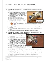
Page 7: ...ks 9 Disconnect the tubing from the cylinder and from the pipeline isolation valve 2 Connecting the pre charge valve to the return port on a sampler probe for continuous sampling of pressurized gas pipeline only 1 Install a valve into the return port of the sampler probe 2 Make sure all valves are closed on the sample cylinder 3 Use small diameter stainless steel tubing to connect from the cylinde...

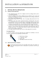
Page 8: ...nd from the pipeline isolation valve 2 3 INSTALLATION If steps 2 2 Section 1 or 2 2 Section 3 are used to pre charge or if the cylinder is being used for continuous sampling and the pre charge is not connected to the pipeline it will be necessary to install an adjustable resetting relief valve in order to relieve pre charge pressure while continuous sampling 1 If your cylinder is equipped with an ...

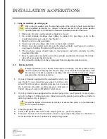
Page 9: ...mount of pressure to exit ensuring that pre charge pressure is relieved steadily 6 When the desired amount of sample is extracted close all valves on the cylinder 7 Close the probe outlet valve 8 Carefully disconnect the cylinder from the probe allowing the trapped product between the probe and cylinder valves to vent 9 Plug or cap all valves on the cylinder 10 Make a note of pressure locations et...

Page 10: ...n the cylinder 10 Record pressure locations etc on the information tag according to company policy Check all fittings for leaks 11 The cylinder is now ready for product removal 2 6 MIXING THE COLLECTED SAMPLE 12 Prior to the analysis of the sample hold the cylinder vertically so the pre charge end is up and the product end is down 13 Allow a moment for gravity to pull the mixer which will slide do...

Page 11: ...rease silicone grease or other before they are installed into the equipment This helps in the installation of the seals while reducing the risk of damage when positioning them on the parts After the seals are installed some additional lubrication can be applied to shafts or cylinder inner diameters to allow smooth transition of parts While lubrication should be thorough only a minimal amount shoul...

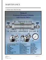
Page 12: ...MAINTENANCE IOM 013 Page 12 of 18 CP2 CP5GM Rev D Last updated 4 14 2011 3 2 MAINTENANCE PARTS DIAGRAM ...

Page 13: ... Push the piston Parts 9 12 and 14 mixing rod Part 8 and mixer Part 7 out of the cylinder using a stick of wood or PVC Be careful not to scratch the surface of the cylinder or the piston 3 Loosen the set screw Part 20 in the piston assembly Disconnect the male piston Part 14 from the ring magnet Part 12 and female piston Part 14 4 Slide the piston off the mixing rod 3 4 MAINTENANCE INSTRUCTIONS Do...

Page 14: ...piston goes toward the pre charge end cap Part 15 and the male end Part 9 goes toward the product side end cap Part 1 3 Carefully slide the cylinder Part 6 to the pre charge end cap Part 13 then carefully slide the six tie bolts Part 17 back into the product end cap Part 13 so that the nuts are facing the outside of the end cap 4 Replace the tracker tube clips Part 3 tracker tube magnet Part 10 an...

Page 15: ...nts of hydrocarbons If hydrocarbons are present in the analysis the system has not been adequately cleaned and further purging will be necessary If hydrocarbons or contaminants remain present a solvent cleaning may be required see step 3 5 3 After cleaning with solvent purge with helium to remove the solvent and analyze the helium to verify the solvent and hydrocarbons have been removed If no hydr...

Page 16: ...lve It is common to see temperature differentials of as much as 100 F 38 C or more Liquid samples that are drawn at 40 to 50 F 40 to 46 C can be transported in shipping cases that may see ambient temperatures as high as 100 F to 160 F 38 to 71 C and at times may exceed 160 F 71 C Operators should be familiar with the basic and general physical properties of the product that they are sampling so th...

Page 17: ...enced a temperature drop There is a defective valve Check all fittings for leaks with leak detector Replace thread sealant Make sure the burst discs are torqued properly If the problem persists the discs may need replacement See Table 2 Restore the temperature to pipeline temperature Repair or restore the defective valve Pressure is leaking across the piston Seals in the piston are leaking Disasse...

Page 18: ...13839 West Bellfort St Sugar Land Texas 77498 1671 Phone 281 491 2331 Fax 281 491 8344 Toll Free 800 776 7267 Web Page www welkereng com ...

Reviews:

Related manuals for CP2GM