18
IOM-222
MODEL: ESSENTIALS™ GAS SAMPLER
REV: A
13839 West Bellfort Street, Sugar Land, TX 77498
welker.com
Service Department 281.491.2331
3.2 Maintenance
If maintenance on the valves or probe is required, the Essentials™ Gas Sampler must be isolated from pipeline pressure and
removed from the pipeline before maintenance can be safely performed.
Prior to performing maintenance, the Essentials™ Gas Sampler must be isolated from pipeline pressure. However, the Essentials™
Gas Sampler does NOT need to be removed from the pipeline to perform
standard
maintenance.
1.
Close product inlet valve A and purge valve B to isolate the Essentials™ Gas Sampler from pipeline pressure (
or
).
2.
Turn OFF electrical power to the system and carefully remove all electrical connections.
3.
Depressurize and disconnect the tubing from all components requiring maintenance.
4.
For complete and proper maintenance on system components, refer to their respective
Installation, Operation, and
Maintenance
(IOM)
Manual
. A list of components is available in
Appendix A, Referenced or Attached Documents,
in this
manual.
5.
After performing necessary maintenance on system components, reconnect all instrument tubing.
6.
Maintenance is now complete. See
Section 2.4, Start-Up Procedures,
returning the Essentials™ Gas Sampler to operation.
If maintenance is performed on the MPS-2, the inline relief needs to be reset. Welker recommends setting the inline relief to 1100
psig unless pipeline pressure drops below 400 psig. See
Section 3.3, Adjusting the Inline Relief,
for instructions on setting the inline
relief.
3.3 Adjusting the Inline Relief
The inline relief is designed to allow product to flow in one direction only. Acting as a check valve, the inline relief will ensure
that sample pumped into the sample cylinder cannot flow back to the pipeline even if pipeline pressure drops.
The inline relief comes factory-set to 1100 psig. The inline relief should not require adjustment unless pipeline pressure drops
below 400 psig or maintenance is performed on the inline relief.
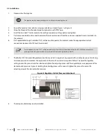
To increase spring tension and raise the relief set point, turn the spring adjuster clockwise.
To decrease spring tension and lower the relief set point, turn the spring adjuster counterclockwise.
Each full clockwise turn of the spring adjuster increases spring tension approximately 100 psig.

