background image

USER’S MANUAL 

Model: FAN-STAND-FREEZE-WL 


ASSEMBLING 


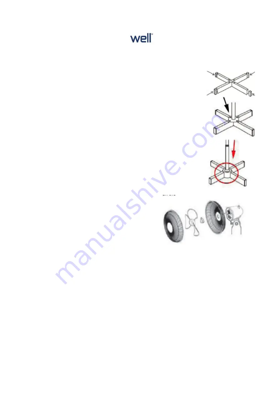
  Take  the  two  base  cross  and  push the  end caps  into  the  ends. 

Cross them over together as draw. 


  Remove the four screws from the base and pole the below tube & 

base to the base. 


  Slide the screw cover down over the adjustable and lower base 

until it’s hide the screws. 


  Replace the pole clamp and raise the adjustable. 

R
e


  Attach  the fan assembly  on  top  of  the upper  tube and  tighten  it 

with retaining screw. 


Place the rear guard onto the motor housing and fix 
it with Central Fixing nut, by screwing back clock 
wise.


Slide fan blade onto the motor spindle ensuring that


notches on the rear line up with the splines on the


shaft.


Screw on the Blade Retaining Nut in


anticlockwise direction.


Hang the front guard over the top of the


rear guard and push the clips inwards


until the front guard is fastened to the


rear guard.


Finally fit the nut and screw through the hole in the


bottom edge of the front guard arrowed and tighten it

.


Summary of Contents for FAN-STAND-FREEZE-WL

Page 1: ...with similar qualification in order to avoid any danger In order to minimize the risk of electric shock in the event of breakedown not to openthe case but to call upon a qualified technician for repairs The item must not be left unattended when it is connected to main supply The item is not to be used if it has been dropped or if there are visible signs of damage This appliance is only intended fo...

Page 2: ...r for remote control 2 Indicator Light On function 3 Speed 3 indicator light 4 Speed 2 Indicator light 5 Speed 1 indicator light 6 Normal Mode indicator light 7 Sleep Mode indicator light 8 4H timer indicator light 9 2H timer indicator light 10 1H timer warning light 11 30 minutes timer indicator light 12 Inactive Button on this model A key Mode Normal or Standby B On and Speed selector C Button t...

Page 3: ...embly on top of the upper tube and tighten it with retaining screw Place the rear guard onto the motor housing and fix it with Central Fixing nut by screwing back clock wise Slide fan blade onto the motor spindle ensuring that notches on the rear line up with the splines on the shaft Screw on the Blade Retaining Nut in anticlockwise direction Hang the front guard over the top of the rear guard and...

Page 4: ...pparatus in a correct socket outlet and connected to the ground Disconnect the power source cable before any operation of cleaning of mentenance and accesories asembly Never modify the appliance in anyway This fan has three types of speed control CONTROL PANEL INSTRUCTION The above button on this panel is inactive for this fan NO FUNCTION REMOTE CONTROL All buttons are the same as below explanatio...

Page 5: ...l light 3 times Speed 3 max will be on and the corresponding pilot light for speed 3 will light TIMER Select between the different setting time by pressing the timer button Each time the valour changes 30min 1h 2h 4h and back to 30min The fan will stay on for the selected amount of time MODE FUNCTION Switch the Mode button between normal and sleep mode On normal mode The motor will run continuousl...

Page 6: ...let or not Check fan blade There s unusual sound when the fan starts Check is fan blade is assembled properly STORAGE Ensure the unit is comletely cool and dry Do not wrap the cord around the appliance as this will cause damage Keep the appliance in a cool dery place and aut of reach from children Waste electrical and electronic equipment are a special waste category collection storage transport t...

Reviews: