background image


Wellav Technologies Ltd.       


16 

UMH 160 Quick Installation Guide 

V1.1-W 

6.2.3 Configuration through WEB Management 


Accessing the equipment through web can be very convenient for remote 

configuration of the equipment. Relative to the front panel settings, web operation 

can provide a more user-friendly man-machine interface, and less limits in space. For 

quick installation, web operation is highly recommended. In this installation guide, 

operation instruction is based on web style. For front panel operation instruction, 

please refer to product user manual.


z

 Preparation 

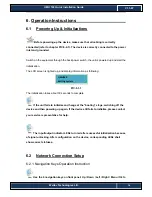
before 

connection 

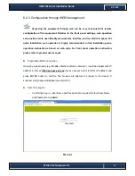
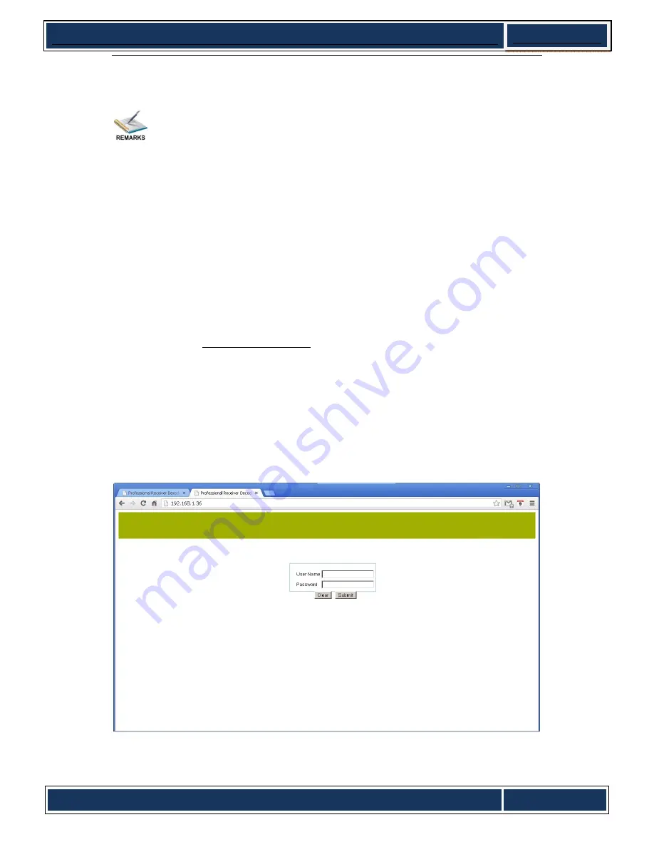
Open any web browser (e.g. Mozilla, internet explorer, safari etc.), input the equipment’s IP 

address in format: 

http://xxx.xxx.xxx.xxx

 (xxx.xxx.xxx.xxx refers to IRD’s IP address) and 

press ENTER button to confirm. The browser will attempt to connect to the device. If 

succeed, a login page will appear (see pic-6-2-1). 


z

  First Time Log On 

o


For first time log on, User Name and Password are required. Default User Name 

and Password are “

admin

”. 


PIC-6.2-1 

Summary of Contents for UMH 160

Page 1: ...Wellav Technologies Ltd 1 UMH 160 Quick Installation Guide V1 1 W UMH160 Integrated Digital Receiver Quick Installation Guide...

Page 2: ...rring by implication estoppel or otherwise any license or right under any copyright or patent whether or not the use of any information in this document employs an invention claimed in any existing or...

Page 3: ...quipment performance reduce or unpredictable results Tips that help you to solve problems or save your time Remarks Additional information to the text in order to emphasize something Revision History...

Page 4: ...a 19 rack 10 5 2 Wiring Connection 12 5 3 Power Connection 13 6 Operation Instructions 14 6 1 Powering Up Initializations 14 6 2 Network Connection Setup 14 6 2 1 Navigation Keys Operation Instruction...

Page 5: ...urce z Do not block ventilation holes of the device so that air can circulate freely z Switch the device off whenever it remains out of service for an extended period z Be sure to turn the device off...

Page 6: ...Check Package and Accessories The Receiver package includes the following accessories z UMH160 Base Unit x1 z Power cord x1 z Earth cord x1 z BNC cord x1 z BNC RCA cord x2 z User manual Disc x1 Please...

Page 7: ...aces Inputs DVB S S2 Input Constellation QPSK 8PSK Symbol Rate 1 45 Mbps FEC All rations compliant with standard Signal Level 65 25 dBm DVB T Input optional Contellation COFDM 2K 8K FTT Symbol Rate 0...

Page 8: ...2xHD SD SDI outputs with embedded digital audio DVB ASI Outputs Connector BNC 75 Packet Length 188 204 byte packets TS Max Bit Rate 72 Mbps TS IP Outputs optional Connector 100 1000Base T RJ 45 FEC Pr...

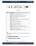
Page 9: ...6 7 8 PIC 4 1 1 Item No Functionality 1 Power status indicator 2 Signal Lock status indicator 3 Alarm status indicator 4 LED displaying screen 5 CI SLOTS 6 KEY PADS including Up Down Left Right arrow...

Page 10: ...nnector for TS input 7 CVBS OUT Output video with BNC interface 8 SDI OUT Output the SDI Video stream 9 ASI OUT Output MPEG 2 or Mpeg 4 TS 10 ETHERNET The port is used in network remote control 11 TUN...

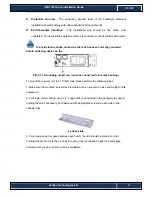
Page 11: ...o mount the receiver unit to a 19 42U rack please perform the following steps 1 Make sure the mounted rack surface is stable and can support the size and weight of this equipment 2 For single unit mou...

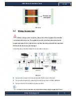
Page 12: ...nded Turn on the devices only after the wiring connection is completed Otherwise the device may be damaged Follow the below connection diagram to set up cable connection PIC 5 2 1 z Set up cable conne...

Page 13: ...usly User only needs to connect one RJ45 cable to the TS IP port of the device 5 3 Power Connection Connect this equipment only to the power sources that are identified on the equipment rating label n...

Page 14: ...information as following PIC 6 1 1 The initialization takes about 30 seconds to complete If the unit fails to initialize and hangs at the booting stage swtiching off the device and then powering up ag...

Page 15: ...b menu by pressing UP and DOWN button and press OK button to change the selected sub menu Step 3 To change parameter settings press RIGHT and LEFT button to move the cursor in which change must be mad...

Page 16: ...is installation guide operation instruction is based on web style For front panel operation instruction please refer to product user manual z Preparation before connection Open any web browser e g Moz...

Page 17: ...is connected to the wrong interface z Main Interface Introduction After logging in successfully it will search the HD IRD which is connected to the server and display it on the left side as below auto...

Page 18: ...tatus tab on the left area and then the status information will show on the right interface as following where you can check the main information of the device PIC 6 3 1 6 3 2 Configure parameters of...

Page 19: ...as input there are three options ASI Tuner and IP here we choose tunel as siganl source After confirm the signal source it is able to go for further configuration Step two Configure the dual RF receiv...

Page 20: ...is is the LNB s local oscillation LO frequency every LNB have one or two oscillation frequencies that can be obtained from the LNB provider or you can check on the LNB label The value is between 5000...

Page 21: ...ng the CAM operation you can determine whether to descramble the program or not o BYPASS to transmit the program without any disposal o CI SLOT 1 CI SLOT 2 Common Interface slot If the program is scra...

Page 22: ...ose IP stream as input source click the sub menu IP Input sub menu in IP menu Then it can turn to the IP parameter interface PIC 6 3 6 Step two Before the receiving of IP signal make sure the IP addre...

Page 23: ...t and protocol shall stay same with that of signal source Step Four Press Submit button to confirm the parameter And press the Status menu in the left area to refresh the receiving information to chec...

Page 24: ...region By changing the program s operation you can determine which program to transmit PIC 6 3 9 If the input signal is not locked or searched the program section shows empty User cannot do any setup...

Page 25: ...igure the information of Audio such as volume and audio language as following PIC 6 3 11 o AUDIO Volume Set the output audio level from 0 to max 49 o AUDIO LANGUAGE Select different audio language if...

Page 26: ...sub menu IP Input in IP menu Then it can turn to the IP parameter interface PIC 6 3 13 Step two Before the setting of IP output channels you should choose the IP channel that you want to use The relat...

Page 27: ...ograms that converted in the IP channel 6 3 3 3 Multicast and unicast for IP z multicast application In multicast application it is simple to connect the physical equipment and the following picture s...

Page 28: ...l decrease even the programs cannot be transmitted through switch or router z unicast application The unicast involves two local area networks connecting each other via Internet Compare with multicast...

Page 29: ...1 W PIC 6 3 17 6 3 5 Check Status again Turn to status page to check if the configuration has come into effect PIC 6 3 18 This is the brief introduce of quick installation if need more detail or compl...

Reviews: