background image

3.3 

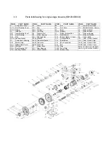
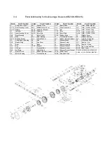
Parts list/drawing for single stage blowers (KB129-KB939) 


ITEM 

PART NAME


ITEM 

PART NAME


ITEM 

PART NAME


ITEM 

PART NAME


01 

Compressor Cover 

04 

Rotor 

08 

Fan 

12 

Upper Terminal Box 

01-1E  Front Bearing Cover 

04-1 

Key 

09 

Fan Cover 

12-1 

Rubber Gasket

Upper

)


01-2E  Nipple 

04-2 

Oil Seal 

10 

Base 

13 

Silencer Mesh 

02 

Impeller 

04-3 

Felt Ring 

10-1E  Support 

14 

Silencer Foam 

02-1 

Inner Bearing Cover 

05 

Stator & Coil 

11 

Under Terminal Box 

15 

Silencer Casing 

02-2 

Front Bearing 

06 

Motor Housing 

11-1 

Cable Gland 

15-1 

Silencer Gasket  

02-3 

Disc 

06-1 

Sponge Filler 

11-2 

Rubber Gasket

 (

Under

)


16 

Inlet / Outlet 

02-1E  Bearing Socket 

06-1E  Bracket 

11-3 

Terminal Board 

16-1 

Inlet

Outlet

Gasket 

03 

Compressor Housing 

06-1S  Capacitor Bracket 

11-4 

Board Base 

16-3 

Inlet

Outlet

Plug 

03-3 

Bronze Ring 

06-2S  Capacitor 

11-5 

Wire Connection 

16-1E  Inlet

Outlet

Plate 

03-1L  Middle Motor Cover 

06-3S  Steel Clip 

11-6 

Nut 

16-2E  Inlet

Outlet

Cover 

03-2L  VA-Seal 

07 

Motor Cover 

11-1E  Plug 

Parts not listed are standard 
ones, e.g.nut,screw, washer


03-3L  Front Bearing WP 

07-1 

Rear Bearing 

11-2E  Steel Plate 

03-4L  Bearing Washer 

07-2 

Wave Washer 

11-3E  Rubber Ring 


Summary of Contents for D66-112015

Page 1: ...Operation Instructions Compressor Vacuum pumps Models D66 112015 Welldana A S All rights reserved Edition 11 2014...

Page 2: ...ation 2 1 Transport and storage 6 2 2 Installation 6 2 3 Electrical connection 10 2 4 Commissioning 11 1 Maintenance 3 1 Cleaning 13 3 2 Lubrication 14 3 3 Parts list drawing for single stage blowers...

Page 3: ...technical data Blowers with limited performance curves in the high pressure range should be fitted with the relative pressure relief valves in order to avoid an overload of the motor Pressure relief...

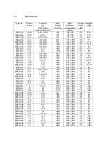
Page 4: ...0 70 70 20 5 22 22 5 22 5 23 23 5 26 KB 529 KB 529L KB 629 KB 629L KB 639 2 2 2 2 3 4 3 4 4 5 6 16 7 5 6 7 2 28 7 2 8 2 312 312 312 312 312 230 230 230 230 260 280 260 280 270 330 72 72 72 72 72 32 33...

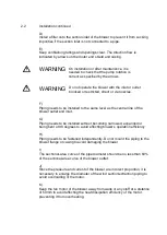
Page 5: ...achine commissioning under favourable circumstances storage in a dry dust free and vibration free room Under unfavourable circumstances this period is considerably reduced 2 2 Installation A Kleeblowe...

Page 6: ...ntly Do not mount the piping to the blower flange or casing to avoid damaging the blower I The sectional area curve of the pipe diameter should be no less than 60 of the sectional area curve of the bl...

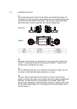
Page 7: ...uild up heat around the outlet of the blower To lead away the heat an iron pipe at minimum 1 meter is thus needed to be connected to the outlet N On the discharge side the cover impeller and silencer...

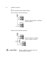
Page 8: ...connection Pressure increases Model A Pressure 90 of Model A Model B Air flow Model A Model B Parallel connection airflow increases Model A Pressure Model A or Model B Air flow Model A Model B Model...

Page 9: ...s are used as power supply high frequency current and voltage harmonics in the motor cables can cause electromagnetic interference Therefore shielded motor cables are recommended D Exceeding the opera...

Page 10: ...properly assembled aligned and connected to piping or hoses as appropriate D The elevation of the installation location is taken into account when adjusting the pressure control valves E The direction...

Page 11: ...hazard for eyes and skins When air is sucked in from the atmosphere the inlet must be covered with protective devices i e gratings in order to prevent foreign elements including parts of the body and...

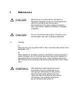
Page 12: ...NG Before any work is performed on the blower or equipment especially covers over moving parts are removed the blower should be properly disconnected from the power supply or frequency drive Wait unti...

Page 13: ...hould have the old grease removed and be recharged with new grease About 50 of the free space in the rolling contact bearings and about 65 of the adjacent grease spaces should be filled with grease B...

Page 14: ...ng 06 Motor Housing 11 1 Cable Gland 15 1 Silencer Gasket 02 3 Disc 06 1 Sponge Filler 11 2 Rubber Gasket Under 16 Inlet Outlet 02 1E Bearing Socket 06 1E Bracket 11 3 Terminal Board 16 1 Inlet Outlet...

Page 15: ...Cover 11 3E Rubber Ring 17 Middle Cover 02 3 Disc 07 1 Rear Bearing 12 Terminal Box Cover 18 Middle Housing 02 1E Bearing Socket 07 2 Wave Washer 12 1 Rubber Gasket Upper 18 1 Impeller Fixing Set 03 C...

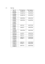
Page 16: ...9 KB 529L KB 629 KB 629L Kb 639 6206ZZCM 6304ZZCM KB 729 KB 829 6207ZC3 6207ZZCM KB 919 KB 929 KB 939 6308ZC3 6209ZZCM KB 2308 KB 2309 KB 2315 6203ZZCM 6202ZZCM KB 3319 KB 3326 6204ZC3 6204ZZCM KB 433...

Page 17: ...again after motor is switched on power consumption is too high Short circuit in the winding Arrange for winding to be inspected Motor overloaded Reduce operating pressure clean filter silencer connec...

Page 18: ...3 7 EC Declaration of Conformity...

Reviews: