background image

24

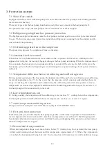
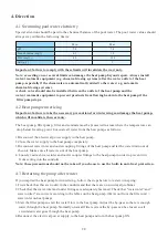
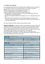
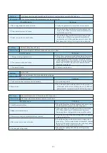
5.3 Failure code table overview

Protection Failure

/

Control
Display

P7

E1

E8

Check

Solution

P1

1. Check the connection of inlet water

sensor.

2. Check if the sensor is broken.

1. Reconnect the sensor.
2. Replace the sensor.

P2

1. Check the connection of outlet water

sensor.

2. Check if the sensor is broken.

1. Reconnect the sensor.
2. Replace the sensor.

P3

1. Check the connection of coil

temperature sensor.

2. Check if the sensor is broken.

1. Reconnect the sensor.
2. Replace the sensor.

P5

1. Check the connection of ambient

temperature sensor.

2. Check if the sensor is broken.

1. Reconnect the sensor.
2. Replace the sensor.

E14

1. Check if there is any blockage  in the

water circuit.

2. Check if the water flow volume is enough.
3. Check if the water pump is working.

1. Remove the cause of the blockage.
2. Increase the water flow volume.
3. Repair or replace the water pump.

E3

1.Check if wiring connection of flow

switch is in correct position.

2.Check  water flow.
3.Check if flow switch is broken.
4.Check if water pump is working.

1.Reconnect the wiring.
2.Increase water flow.
3.Replace flow switch.
4.Repair or replace water pump.

Check the connection

Reconnect the connection wire.

P7

No action required

No action required

Winter anti-freeze protection

Water flow switch failure

Protection for excessive temp.
difference between water inlet & outlet

Ambient temp. sensor failure

Coil temp. sensor failure

Outlet water temp. sensor failure

Inlet water temp. sensor failure

Communication failure

High pressure protection

Winter anti-freeze protection

E4

Order of phases incorrect
(only for 3 phase model)

Order of phases incorrect

Reconnect the phases in right order.

E2

1. Check if high pressure switch is broken.
2. Check if there is a blockage  in water

circuit or water flow is not enough.

3. Check if there is a blockage in refrigerant

circuit.

1. Replace  high pressure switch.
2. Remove cause of blockage  or

increase water flow.

3. Send heat pump to dealer for detailed

check.

1. Check if low pressure switch is broken.
2. Check if  refrigerant level is low.
3. Ambient temp. and water inlet

temp. is too low.

1. Replace  low pressure switch.
2. Fill up with enough refrigerant.
3. Decrease water flow.
4. Send heat pump to dealer for

detailed check.

Low pressure protection

Water Out Over-Heated

1. Check if there is any jam in the water circuit.
2. Check if the water flow volume is enough.
3. Check if the water pump has failed to work.

1. Remove the jam.
2. Increase the water flow volume.
3. Repair or replace the water pump.

E12

E13

Water Out Over-Cooled

P4

1. Check the connection of return gas

temperature sensor.

2. Check if the sensor is broken.

1. Reconnect the sensor.
2. Replace the sensor.

Return gas temp. sensor failure

Summary of Contents for WMV

Page 1: ...SWIMMING POOL HEAT PUMP UNIT Installation Instruction Manual Rev WF PHP 20 10 2016 1 27 1000115...

Page 2: ...earth the heat pump in order to prevent electric shocks caused by an unexpected short circuit in the unit 4 4 There is a diagram of the wiring in this manual 4 5 For safety reasons you should not rep...

Page 3: ...2 2 13 Operation of APP controller 2 2 1 13 working principle of APP control 2 2 2 13 Set up of the network 2 2 3 15 APP operation 3 Protection systems 3 1 19 Water flow switch 3 2 19 Refrigerant gas...

Page 4: ...sting water pump circulates the water through the heater usually next to the pool equipment and the water warms up The heat pump timer could be set to operate during daylight hours for example usually...

Page 5: ...tion Do not place the unit in an enclosed area with a limited air volume where the unit s discharged air will be re circulatedor near shrubs that could block the air inlet These locations deny the uni...

Page 6: ...and the soil surrounding the pipe which translates to an operation time increase of 3 5 1 5 Installation of the check valve Attention When using automatic chlorine and PH dosage systems it is of utter...

Page 7: ...Valve 2 Valve 3 BY PASS F r o m f i l t e r T o p o o l OUT IN HEATPUMP Power cable inlet Heat Pump Outlet Inlet Condensed water draining pipe Draining nozzle Discharge water to pool Pool water inlet...

Page 8: ...rofessional technician It is strongly advised to place a protective guard around the unit to keep children away from the heat pump An authorized electrician must connect the Heat Pump to the power 230...

Page 9: ...ture of the pool water drops more than 1 C below the set temperature Water flow switch the unit is equipped with a flow switch that is switched on when enough water has flowed through the unit and tha...

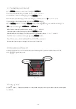
Page 10: ...to mode TIMER button Timer button to set timer on and timer off To enter parameter settings and confirm settings button To increase or decrease value Icons definitions heating icon showing heat pump i...

Page 11: ...2 shows heat pump in standby status and figure 2 3 shows heat pump in running status The left temperature shows flow water temperature while the right temperature is the return water temperature Figu...

Page 12: ...details parameter value Note All parameters can be changed ONLY under standby status 2 1 4 Adjust desired water temperature 1 First select desired mode auto heating or cooling 2 No matter the heat pum...

Page 13: ...again to unlock 2 1 9 Key pad lock Figure 2 6 If the starting time is set to be the same as the finishing time then the timer function is off The signal will be off key and locked Timer ON OFF Minute...

Page 14: ...op Adjustable By technician Adjustable By technician By technician By technician By technician By technician By technician By technician Adjustable By technician 4 way valve direction Four way Valve D...

Page 15: ...tart Time delay of filter pump stop after compressor stop Setting Ambient temp to Start bottom heater Change Fahrenheit Celsius 0 C 1 F Factory reset Set W Out Over Cooling Prot Protection In Out Cool...

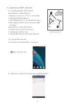
Page 16: ...work operation 2 2 1 working principle of APP control Requirements for Android System 1 System version above 2 3 7 2 3 7 not included 2 Resolution 480 800 and above 3 APK 40M and above TF card or buil...

Page 17: ...symbol on control display 4 Click the POOL COMFORT icon and start it wifi name wifi password 5 Click button and choose new device With the connected WIFI name shown fill in WIFI password and click Sea...

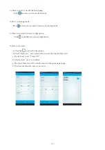
Page 18: ...he main interface There will be a gentle reminder of changing the password Set the new password and it will go to operational page Now the connection between your heat pump and APP are well set up 1 I...

Page 19: ...set desired water temperature Click to modify the water temperature 5 How to set timer a Click the to enter the timer page b Click Timer On move up and down to set the time for Timer On d Finally cli...

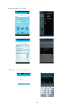
Page 20: ...ed to change the factory default setting only available for technician Insert technical password to enter technical setting page In running or standby status click to check system measured value and w...

Page 21: ...18 9 How to change user s password 8 How to rename the device POOL COMFORT POOL COMFORT...

Page 22: ...ration of the heat pump the temperature difference between inflowing and outflowing water will approximate 1 to 2 In the event that the pressure switch does not work and that the water stops circulati...

Page 23: ...t of the heat pump and the water treatment equipment to prevent products from flowing back into the heat pump if the filter pump stops 1 Disconnect the electrical power supply to the heat pump 2 Close...

Page 24: ...easily accessible 2 Keep the area surrounding the heat pump free of organic waste 3 Prune any vegetation around the heat pump so that there is sufficient free space around the pump 4 Remove any water...

Page 25: ...esn t make a sound Possible cause No electrical power supply Solution Check power supply wiring fuses 5 2 Trouble shooting guide attempt to modify the internal configuration of the heat pump DO NOT 1...

Page 26: ...the problem persists have the heat pump checked by a refrigeration technician Problem Observation Possible cause Solution water leak there s an amount of water under the heat pump 1 Condensation due t...

Page 27: ...tection Water flow switch failure Protection for excessive temp difference between water inlet outlet Ambient temp sensor failure Coil temp sensor failure Outlet water temp sensor failure Inlet water...

Page 28: ...25 6 Name plate wiring diagram 6 1Name plate...

Page 29: ...26 6 2 Wiring diagram...

Reviews: