33
Thank you for placing your trust in our company by purcha-
sing the Weller WD 2 (M). Production was based on stringent
quality requirements which guarantee the perfect operation
of the device.
1. Important!
Please read these Operating Instructions and the attached
safety information carefully prior to initial operation. Failure
to observe the safety regulations results in a risk to life and
limb.
The manufacturer shall not be liable for damage resulting
from misuse of the machine or unauthorised alterations.
The Weller microprocessor-controlled soldering station
WD 2 (M) corresponds to the EC Declaration of Conformity in
accordance with the basic safety requirements of Directives
89/336/EEC and 73/23EEC.
2. Description
2.1 Control unit
The microprocessor-controlled 2-channel soldering station
WD 2 (M) is part of a generation of devices which have been
developed for industrial production technology, including
repair and laboratory areas. Digital control electronics and
high-quality sensor and heat transmission technology in the
soldering tool guarantee precise temperature control beha-
viour at the soldering tip.
Top temperature accuracy and optimised, dynamic tempera-
ture behaviour when under stress is achieved by fast and
precise measured value recording in the closed control loop.
The soldering tools themselves are recognised automatical-
ly by the WD 2 and the corresponding control parameters
assigned. This means that recalibration can usually be avoi-
ded.
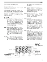
Various potential balancing options (8) for the soldering tip
and an antistatic design of the control unit and soldering iron
add to the high quality standard. A custom-designed calibra-
tion function, an offset value input option, programmable
temperature decrease (setback) and standby and interlock
functions extend the functional diversity of this unit.
The desired temperature can be set in the range 50 °C –
450 °C (150 °F – 850 °F). Specified and actual values are
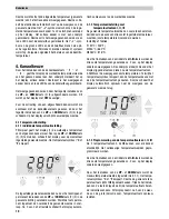
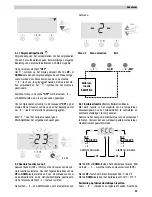
displayed digitally. Three temperature buttons (4) (5) (6) are
used for direct selection of the fixed temperatures. When the
preselected temperature has been reached, the visual con-
trol check flashes to indicate this ("
" symbol in the display
and additional green LED).
If a USB port is available, the soldering unit can be remotely
controlled by means of PC software and temperatures can
be read out and documented.
2.2 Safety rest
When not in use, the soldering iron must always be placed
in the safety rest.
English
Technical data
Dimensions:
(L x W x H mm) 134 x 108 x 147; (L x W x H inch) 5,27 x 4,27 x 5,77
Mains voltage:
230 V / 50/60 Hz
120 V / 60 Hz
100 V / 50/60 Hz
Power input:
160 W
Protection class:
I (control unit), III (soldering iron)
Fuse (12):
T500mA
(230 V / 50/60 Hz)
T1.6A
(120 V / 60 Hz)
T1.6A
(100 V / 50/60 Hz)
Temperature control:
50 °C – 450 °C (150 °F – 850 °F); WSP 150: 550°C (999°F)
Temperature accuracy:
±9°C (±17 °F)
Temperature stability:
±5 °C (±9 °F)
Leak resistance of soldering
< 2
Ω
tip: (tip to ground)
Leak voltage of soldering tip:
< 2 mV
(tip to ground)
Summary of Contents for WD 1M
Page 8: ...WD 2 ...
Page 9: ...WD 2M ...
Page 179: ...170 Setback function ...
Page 180: ...171 USB interface ...
Page 181: ...172 Exploded Drawing WD 2 WD 2 ...
Page 182: ...173 Circuit Diagram WD 2 ...
Page 183: ...174 Exploded Drawing WD 2M WD 2M ...
Page 184: ...175 Circuit Diagram WD 2M ...

