35
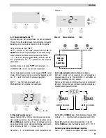
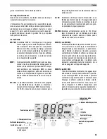
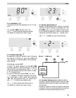
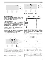
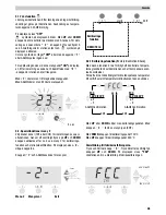
Following this, the set temperature (specified value) of the
active channel is displayed for a brief period. After this, the
electronics system switches automatically to the actual value
display. The "
" symbol appears and set temperatures for
channel 1 and 2 appear in small form in the display. The acti-
ve channel is labelled with an arrow underneath it. In additi-
on to this, the displayed channel is labelled by a red LED next
to the connection socket. The "
" symbol and the green
LED on the connection socket are used as a visual control
check. When lit up permanently, this indicates that the
system is heating up. Flashing indicates that the service
temperature has been reached.
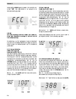
4. Channel selection
When the channel selection butto
1
or
2
is pres-
sed, the display shows the temperature actual value of the
selected channel. The channel that is active in the display is
labelled with an arrow underneath it. In addition to this, the
displayed channel is labelled by a red LED over the connec-
tion socket.
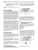
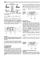
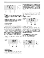
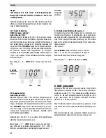
The displayed channel can be switched off by simultaneous-
ly pressing the
UP
and
DOWN
buttons (2) (3). This is confir-
med in the display with
OFF
.
To activate a deactivated channel, select it using the channel
selection button, if necessary, and simultaneously press the
UP
and
DOWN
buttons (2) (3) to switch it on. The actual value
appears in the display.
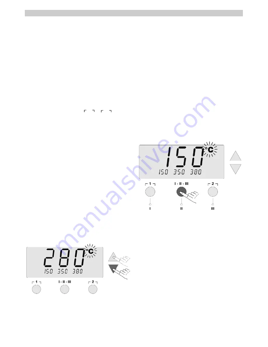
4.1 Temperature setting
4.1.1 Individual temperature setting
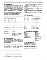
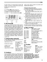
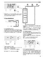
As a rule, the display (1) shows the temperature actual value
of the selected channel. When the
UP
or
DOWN
button is
pressed (2) (3), the display switches to the currently set spe-
cified value. The temperature symbol
°C
or
°F
flashes.
The specified value can now be changed by tapping or hol-
ding in the
UP
or
DOWN
button (2) (3) in the corresponding
direction. If the button is pressed permanently, the specified
value changes in fast mode. Approx. 2 seconds after the but-
ton is released, the display switches automatically back to
the actual value.
4.1.2 Temperature setting using the temperature
buttons I, II, III
The specified value for the temperature can be changed
separately for each channel by selecting three preset tempe-
rature values (fixed temperatures).
Factory setting:
I
150 °C ( 300 °F)
II
350 °C ( 662 °F)
III
380 °C (716 °F).
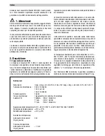
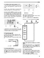
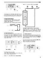
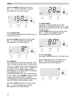
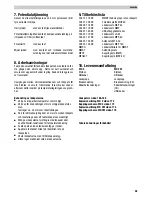
When the middle
I-II-III
button is pressed, the three fixed
temperatures are shown at the bottom of the display for
approx. 2 seconds. The arrow underneath disappears. The
buttons under the display now serve as temperature buttons
I, II, III
for the displayed fixed temperatures. While the tem-
perature symbol is flashing, the temperature can be selected
with the three temperature buttons. After this, the display
switches back automatically to the actual value display.
4.1.3 Assignment of the temperature buttons I, II, III
The 3 temperature buttons
I, II, III
can be assigned any tem-
perature values for each channel separately.
When the middle
I-II-III
button is pressed, the three fixed
temperatures are shown at the bottom of the display for
approx. 2 seconds.
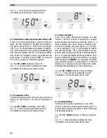
When the
UP
or
DOWN
button is pressed, the new tempera-
ture value is set (see 4.1.1). The temperature symbol
°C
or
°F
flashes. Following this, press and hold in the desired tem-
perature button
I, II
or
III
. When the button is pressed, the
small display assigned to the temperature button also flas-
hes and, after 3 seconds, adopts the value of the large dis-
play. Release the temperature button again.
English
Summary of Contents for WD 1M
Page 8: ...WD 2 ...
Page 9: ...WD 2M ...
Page 179: ...170 Setback function ...
Page 180: ...171 USB interface ...
Page 181: ...172 Exploded Drawing WD 2 WD 2 ...
Page 182: ...173 Circuit Diagram WD 2 ...
Page 183: ...174 Exploded Drawing WD 2M WD 2M ...
Page 184: ...175 Circuit Diagram WD 2M ...


