4
Refer to Tool Troubleshooting Guide
Calibrate station according to Tip Temperature Offset Procedure.
HIGH TIP VOLTAGE
Replace soldering tool with known good tool and recheck tip voltage.
·
Refer to Tool Troubleshooting Guide
·
Check for continuity from pin #5 of tool receptacle to line cord ground pin.
·
Check wiring from tool receptacle to line cord ground pin - repair if defective.
MODEL PES51 50 WATT SOLDERING TOOL
PRODUCT DESCRIPTION
The Weller
®
PES51 Soldering Pencil features a Nichrome wound, Stainless Steel heating element construc-
tion. A non-burning silicone rubber cord and a large selection of Iron, Nickel and Chrome Plated, Copper tips in
various styles, including tips for surface mount devices. The handle design is lightweight, high impact ESD
plastic, with controlled thermal conductivity via a foam sleeve to allow continuous use without discomfort from
heat or fatigue. The heating element is a fast response, long life, Nichrome wound, unit encased in stainless
to eliminate corrosion at high temperature.
The Weller
®
PES51 tools are interchangeable without the need to make any adjustments to the station Offset
function. This is made possible by the use of a precision temperature sensor; which is positioned deep inside
the tip to insure rapid response to soldering load variations.
The Weller
®
PES51 tool has been specifically designed for use at electrostatic free workstations and is
completely free from stored static charges. The plastic used in this product meets the requirements for
Electrostatic Protective Materials. All Weller
®
ESD tools comply with DOD-HDBK-263.
The Weller
®
PES51 tool is designed to be used with the WES51 and WESD51 series power units. The station
and tool combination meets DOD-STD-2000, MIL-S-2000, MIL-S-45743, W-S-570 as well as DOD-STD-1686.
PES51 SERIES SOLDERING TOOL TROUBLESHOOTING GUIDE
CAUTION: Disconnect from power unit before attempting repairs.
NOTE: If ground pin has been removed from power unit line cord, tip temperature control may
be erratic.
1. Tool does not heat.
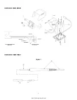
1.1 Check heater resistance from pin 2 to pin 6
(see Figure 1)
of the tool connector, should measure 9 -
11 ohms.
1.1.1 Proceed to 1.2 if heater is correct.
1.1.2 Refer to PES201 Replacement Heater/Sensor Instruction Sheet before disassembling (
see
PES201 Replacement Heater Instruction Sheet
).
1.1.2.1 Remove tip barrel nut assembly and tip.
1.1.2.2 Attach 3/8 - 24 nut to heater.
1.1.3 Release cord strain relief by pushing cord 1/4" to 1/2" into handle (
see PES201 Replacement
Heater
Instruction Sheet
).
1.1.3.1 Clamp 3/8 - 24 nut in vise, pull handle from side-to-side to disengage heater.
1.1.4 Replace cord/handle assembly if heater is correct; else replace heater/sensor assembly.
Complete instructions are provided with replacement part.


