15
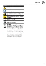
WARNING
Fire and explosion hazard!
The unit is not permitted to be used for the extraction of
inflammable gases.
The unit must not be exposed to temperatures above
50°C, naked flame or condensed solvents.
The organisation operating the unit is responsible for the
observance of the legal limits for noxious substances at
the place of work.
The filtration system may only be put into operation if it is
in perfect working order.
Intended use of the soldering station/ desoldering
station also includes the requirement that you
adhere to these instructions,
observe all other accompanying documents,
comply with national accident prevention guidelines
applicable at the place of use..
The manufacturer will not be liable for unauthorised
modifications to the device.
User groups
Due to differing degrees of risk and potential hazards, sever-
al work steps may only be performed by trained experts.
Work step
User groups
Installation of complex
pipe systems with
multiple extractor arms
connected
Specialist personnel with
technical training
Technical trainees under the
guidance and supervision of
a trained expert
Replacing electrical repla-
cement parts
Electricians
Technical trainees under the
guidance and supervision of
a trained expert
Specification of mainte-
nance intervals
Safety expert
Operation
Filter change
Non-specialists
Operation
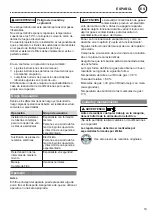
Notice
The unit may emit dust from the main filter after trans-
portation. Make sure that the unit is put into service in
a suitable room.
CAUTION
A high noxious gas concentration will
cause the activated charcoal to heat up.
To avoid overheating, the unit should be run without
noxious gases for several minutes before switching off.
Put the tool into operation as described in the chapter
„Placing into operation“.
Please adhere to the operating instructions of the
connected devices.
Check to see if the mains voltage matches the ratings
on the nameplate.
Make sure the machine is switched off before plugging
in.
Optimal gas filtration is achieved as follows:
Temperature of process air in gas filter < 38 °C
Relative humidity < 60 %
Gas molecules > 30 g/mol (better filtration results are
achieved with larger molecules)
Boiling point of the gas molecules > 0 °C
Care and maintenance
WARNING
Before doing any work on the machine, pull the
plug out of the socket.
The unit must not be altered or modified in any way!
Repairs must always be referred to a Weller-trained
specialist.
Use original replacement parts only.
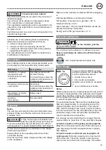
Filter change
year
MIN 1x
To ensure that the filtration system
functions properly, the compact filter
must be replaced as follows
at least once a year or
if the maximum allowable
workplace concentration is exceeded
or
as per maintenance schedule
Notice
Different fluxes and flux constituents and the amount of
and size of dust particles in the extracted air will signifi
cantly effect the filters working life. Submicron particles
in the extracted air increase when soldering or welding
to varnish insulated wire.
The suspended matter filter and the broadband gas
filter are complementary to one another and can be
replaced together as a compact filter. The compact
filter must be changed once a year in order to ensure
it is fully functional. The fine dust filter (filter mat) is the
preliminary stage of the compact filter and therefore
must be replaced more frequently.
It is strongly recommended that the compact filter be
replaced after no more than 10 fine dust filter changes.
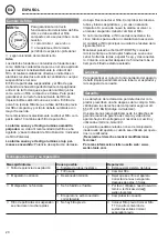
An alarm sounds and the yellow warning light fla-
shes:
Recommended service life of filter has expired.
(see Operating time filter display/Extraction capacity
filter display)
An alarm sounds and the red warning light is lit
continuously:
Extraction capacity is too low. Switch
off the filter unit. Check the nozzles, tubes and ext-
ractor arms, and clean them if necessary. If the alarm
GB
ENGLISH
Summary of Contents for Zero Smog TL
Page 52: ...50 H v 8 v v v o vo v v v v o v ouv v v o v vo o ov v vo T v v o v O v v v Weller F7 GR...
Page 53: ...51 50 C 38 C 60 30 g mol 0 C Weller WELLER GR...
Page 93: ...91 50 C 38 C 60 30 g mol 0 C Weller WELLER BG...
Page 104: ...102 Weller F7 RU P...
Page 105: ...103 50 C 38 C 60 30 0 C Weller WELLER RU P...
Page 108: ...106 8 PE Weller F7 50 C 38 C 60 30 g mol 0 C CN...
Page 111: ...109 PE Weller F7 50 C KO...
Page 114: ...112 Weller F7 50 C JP...
Page 115: ...113 38 C 60 30 g mol 0 C Weller year MIN 1x 1 1 1 1 10 5 UP DOWN 5 5 JP...
Page 117: ...115 JP ESD ESD CE...
Page 118: ...116 Zero Smog TL...


