ASSEMBLY
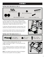
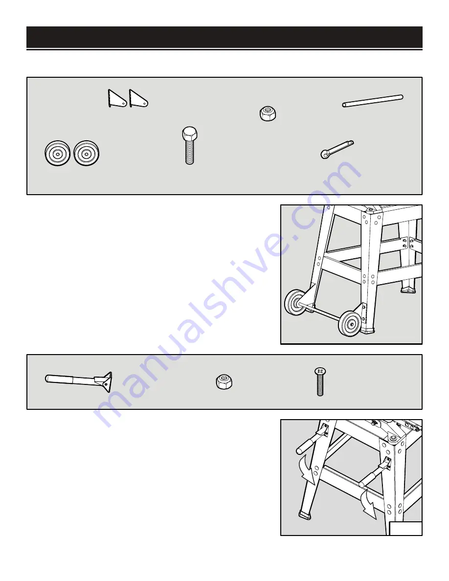
INSTALLING THE WHEELS (FIG.3)
1. Attach the 2 wheel brackets to the 2 wheel-mounting
legs with (4) M8-1.25 x 16 hex bolts and (4) M8-1.25 lock
nuts. Note that the left and right wheel brackets are different
configurations. Tighten the fasteners with a wrench.
2. Slide the wheel axle through the 2 wheel brackets. Then
install the two wheels onto the two ends of the wheel axle.
3. Secure the 2 wheels with the 2 cotter pins by inserting
them through the axle holes and bending back the ends.
INSTALLING THE HANDLES (FIG. 4)
1. Attach the lifting handle assemblies onto the
handle-mounting with (4) M6-1 x 10 flat head screws and
(4) M6-1 lock nuts.
2. Use a Phillips screwdriver to hold the mounting screws
stationary while tightening the locking nuts with a suitable
wrench.
NOTE:
The handle should be able to swing up 90 degrees
from the “down” position, but not any farther.
Wheel Brackets (x2)
Wheels (x2)
Wheel Axle (x1)
M8-1.25x16 Hex Bolts (x4)
M8-1.25 Lock Nuts (x4)
Cotter Pins 4x20mm (x2)
Lifting Handle
Assemblies (x2)
M6-1 x 10 Flat
Head Screws (x4)
M6-1 Lock
Nuts (x4)
Fig. 3
Fig. 4
11
Summary of Contents for 65911
Page 35: ...35 NOTES ...
Page 36: ...THANKS FOR REMEMBERING ...


