ASSEMBLY & ADJUSTMENTS
ADJUSTING THE WORK TABLE BEVEL
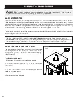
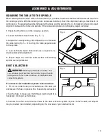
The work table has the capacity to tilt from 0 to 45 degrees
for sanding bevels on your workpiece. For any bevel sand-
ing operation, you must use throat plate with an oblong-
shaped opening.
To adjust the table bevel:
1. Disconnect the machine from the power source.
2. Loosen the table bevel knobs (Fig. 3 - 1) on both sides
of the sander.
3. Tilt the table until the pointer is indicating the desired
angle on the bevel gauge.
4. Re-tighten both bevel knobs.
MACHINE MOUNTING
For safe operation, the machine must be secured onto a flat, secure workbench or stand. The base of the ma-
chine has four 6 mm mounting holes. Place the sander on the mounting surface, and insert a pencil through
the mounting holes to mark the hole locations. Remove the sander and drill out the mounting holes. Then align
the sander base over the mounting holes and secure the machine using four mounting bolts, washers, locking
washers and hex nuts (mounting hardware not included). Securely tighten the hex nuts.
For temporary mounting, secure the sander to a mobile mounting board and use 2 large C-Clamps to secure
the mounting board to a solid surface.
TIP:
Your spindle sander is compatible with the
WEN 6588
Multipurpose Planer Stand, available at
wenproducts.com
. Forget measuring and drilling holes on your workbench, simply mount your machine
onto the stand with pre-drilled holes, and transport your machine around the workshop with ease.
Fig. 3
1
12
WARNING:
To prevent accidental starting, make sure the machine is switched OFF and the power
plug is disconnected before assembly, setting up or making adjustments.


