background image

1. EXAMINE EXTENSION CORD BEFORE USE. Make sure your extension cord is properly wired and in good 
condition. Always replace a damaged extension cord or have it repaired by a qualified person before using it.
 
2. DO NOT ABUSE EXTENSION CORD. Do not pull on cord to disconnect from receptacle; always disconnect 
by pulling on plug. Disconnect the extension cord from the receptacle before disconnecting the product 
from the extension cord. Protect your extension cords from sharp objects, excessive heat and damp/wet 
areas.

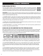
3. USE A SEPARATE ELECTRICAL CIRCUIT FOR YOUR TOOL. This circuit must not be less than a 12-gauge 
wire and should be protected with a 15A time-delayed fuse. Before connecting the motor to the power 
line, make sure the switch is in the OFF position and the electric current is rated the same as the current 
stamped on the motor nameplate. Running at a lower voltage will damage the motor.

When using an extension cord, be sure to use one heavy enough to carry the current your product will draw. 
An undersized cord will cause a drop in line voltage resulting in loss of power and overheating. The table 
below shows the correct size to be used according to cord length and ampere rating. When in doubt, use a 
heavier cord. The smaller the gauge number, the heavier the cord. 

AMPERAGE

REQUIRED GAUGE FOR EXTENSION CORDS

25 ft.

50 ft.

100 ft.

150 ft.

3.5A

18 gauge

16 gauge

16 gauge

14 gauge

GUIDELINES AND RECOMMENDATIONS FOR EXTENSION CORDS

ELECTRICAL INFORMATION

IMPORTANT: 

Servicing a double-insulated product requires extreme care and knowledge of the system, and 

should be done only by a qualified service personnel using identical replacement parts. Always use original 
factory replacement parts when servicing. 

1. POLARIZED PLUGS. To reduce the risk of electric shock, this equipment has a polarized plug (one blade is 
wider than the other). This plug will fit in a polarized outlet only one way. If the plug does not fit fully in the 
outlet, reverse the plug. If it still does not fit, contact a qualified electrician to install a proper outlet. Do not 
modify the machine plug or the extension cord in any way. 

2. GROUND FAULT CIRCUIT INTERRUPTER PROTECTION (GFCI) should be provided on the circuit or outlet used 
for this power tool to reduce the risk of electric shock.

3. SERVICE AND REPAIR. To avoid danger, electrical appliances must only be repaired by qualified service 
technician using original replacement parts.

DOUBLE-INSULATED TOOLS

The tool’s electrical system is double insulated where two systems of insulation are provided. 
This eliminates the need for the usual three-wire grounded power cord. Double insulated tools do 
not need to be grounded, nor should a means for grounding be added to the product. All exposed 
metal parts are isolated from the internal metal motor components with protecting insulation. 

8

Summary of Contents for AT6535

Page 1: ...ntion to the rules for safe operation warnings and cautions If you use your tool properly and for its intended purpose you will enjoy years of safe reliable service IMPORTANT MODEL AT6535 OSCILLATING SPINDLE SANDER NEED HELP CONTACT US 800 232 1195 M F 8am 5pm CST techsupport wenproducts com WENPRODUCTS COM Have product questions Need technical support Please feel free to contact us at NOTICE Plea...

Page 2: ...0 Hz 3 5A Motor Speed No Load 2000 RPM Spindle Oscillation No Load 58 OPM Spindle Diameter 1 2 Rubber Drum Diameter 4 3 4 1 1 1 2 2 19 mm 26 mm 38 mm 51 mm Sanding Sleeve Diameter 5 1 2 3 4 1 1 1 2 2 80 Grit 13 mm 19 mm 26 mm 38 mm 51 mm Dust Port Size 2 O D 1 7 8 I D Work Table Bevel Angle 0º to 45º Table Dimensions 14 1 2 x 14 1 2 in IP Rating IP20 Product Net Weight 33 2 lbs Assembled Dimension...

Page 3: ... to cover all possible conditions and situations that may occur WEN reserves the right to change this product and specifications at any time without prior notice Keep this manual available to all users during the entire life of the tool and review it frequently to maximize safety for both yourself and others SAFETY ALERT SYMBOL Indicates danger warning or caution The safety symbols and the explana...

Page 4: ...ck 2 Avoid body contact with earthed or grounded surfaces such as pipes radiators ranges and refrigerators There is an increased risk of electric shock if your body is earthed or grounded 3 Do not abuse the cord Never use the cord for carrying pulling or unplugging the power tool Keep cord away from heat oil sharp edges or moving parts Damaged or entangled cords increase the risk of electric shock...

Page 5: ...ny power tool that cannot be con trolled with the switch is dangerous and must be repaired 3 Disconnect the plug from the power source and or the battery pack from the power tool before making any adjustments changing accessories or storing power tools Such preventive safety measures reduce the risk of starting the power tool accidentally 4 Store idle power tools out of the reach of children and d...

Page 6: ... sanding sleeves before operation Always unplug the unit before making adjustments or changing sandpaper rubber drums or throat plates Always use the throat plate that matches the diameter of the drum to minimize the gap between the drum and the throat plate opening this will reduce the risk of personal injury 7 WORKPIECE REQUIREMENTS Only stand workpieces sturdy enough to withstand the force of t...

Page 7: ...ents to clean plastic parts Solvents could dissolve or otherwise damage the material Use only a soft damp cloth to clean plastic parts 17 PART REPLACEMENTS Should any component of your sander be missing damaged or fail in any way shut off the switch and remove the plug from power supply outlet Replace the missing damaged or failed parts using only identical replacement parts before resuming operat...

Page 8: ...EXTENSION CORDS 25 ft 50 ft 100 ft 150 ft 3 5A 18 gauge 16 gauge 16 gauge 14 gauge GUIDELINES AND RECOMMENDATIONS FOR EXTENSION CORDS ELECTRICAL INFORMATION IMPORTANT Servicing a double insulated product requires extreme care and knowledge of the system and should be done only by a qualified service personnel using identical replacement parts Always use original factory replacement parts when serv...

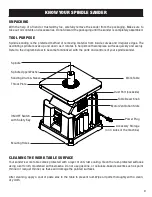
Page 9: ...eferred method of removing material from inside curves and irregular edges The oscillating spindle moves up and down as it rotates to help smooth workpiece surfaces quickly and evenly Refer to the diagram below to become familiarized with the parts and controls of your spindle sander CLEANING THE WORK TABLE SURFACE Your sander s work table comes protected with a layer of anti rust coating Clean th...

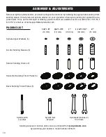
Page 10: ...t our customer service at 800 232 1195 M F 8 5 CST or email us at techsupport wenproducts com Rubber Sanding Drums 4 80 Grit Sanding Sleeves 5 Bevel Sanding Throat Plates 5 Spindle Upper Washers 5 Horizontal Sanding Throat Plates 5 13 mm 1 2 5 19 mm 3 4 75 26 mm 1 38 mm 1 1 2 1 5 51 mm 2 Spindle with Lock Nut Spindle Wrenches 2 14 20 mm Spindle Nut Wrench PACKING LIST Sanding sleeves of various gr...

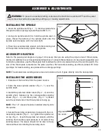
Page 11: ...for bevel sanding use plates with an oblong openings NOTE The smallest size sanding sleeve does not include a drum It goes directly onto the bare spindle INSTALLING THE ACCESSORIES 1 Disconnect the machine from the power source 2 Slide the lower spindle washer Fig 2 1 over the spindle shaft 3 Install the preferred rubber drum Fig 2 2 onto the spindle shaft followed by the corresponding sanding sle...

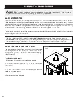
Page 12: ...encil through the mounting holes to mark the hole locations Remove the sander and drill out the mounting holes Then align the sander base over the mounting holes and secure the machine using four mounting bolts washers locking washers and hex nuts mounting hardware not included Securely tighten the hex nuts For temporary mounting secure the sander to a mobile mounting board and use 2 large C Clamp...

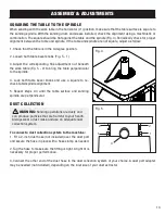
Page 13: ...Fig 5 2 to bring the table perpendicular to the spindle 4 Lock both table bevel knobs and use a square to re check table spindle alignment 5 Repeat steps 2 4 until the table surface and sanding spindle are perpendicular Fig 4 Fig 5 WARNING Sanding operations are dusty and can produce particles that are harmful to your health Always wear a dust mask and use an adequate dust collection system To con...

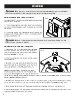
Page 14: ...he sander has come to a complete stop by gently pulling the key out If you guide the workpiece in the opposite direction the forces of the spinning sanding sleeve will tend to throw or bounce the workpiece away from the sanding sleeve possibly resulting in injuries 4 Maintain downward pressure on the workpiece against the table gently working it along the sanding sleeve until the desired curve has...

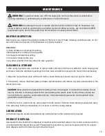
Page 15: ...nce or lubrication work WARNING Any attempt to repair or replace electrical parts on this tool may be hazardous Ser vicing of the tool must be performed by a qualified technician When servicing use only identical WEN replacement parts Use of other parts may be hazardous or induce product failure CAUTION Most plastics are susceptible to damage from various types of commercial solvents Do not use an...

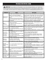
Page 16: ...sure on workpiece while sanding 4 Keep workpiece moving while sanding on the sanding sleeve Burns on workpiece 1 Using a sanding grit that is too fine 2 Using too much pressure 3 Work held still for too long 4 Sanding sleeve loaded with debris 1 Use a coarser grit sanding accessory 2 Reduce sanding pressure on workpiece 3 Do not keep workpiece in one place for too long 4 Clean or replace the sandi...

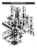
Page 17: ...2 33 34 35 38 39 40 41 42 33 43 44 45 46 36 37 47 48 49 50 43 44 51 52 48 47 53 36 37 54 54 55 35 34 47 56 57 58 60 61 62 63 66 67 68 70 71 33 69 69 70 68 67 71 33 72 73 74 75 76 77 78 79 47 80 81 82 83 84 85 6 86 87 88 89 90 91 92 94 95 96 97 98 99 20 21 22 100 101 102 103 104 72 105 106 107 108 109 110 111 112 79 47 113 118 112 114 115 116 20 21 22 93 17 ...

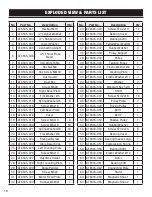
Page 18: ...le Pointer 1 30 AT6535 030 Screw M4x6 1 31 AT6535 031 Motor Fixed Plate 1 32 AT6535 032 Rubber Washer 1 No Part No Description Qty 33 AT6535 033 Screw ST4 2x13 12 34 AT6535 034 Bearing Cover 2 35 AT6535 035 Bearing 6203 2 36 AT6535 036 Felted Wool Washer 2 37 AT6535 037 Rubber Washer 2 38 AT6535 038 Pulley Support 1 39 AT6535 039 Pulley 1 40 AT6535 040 Tension Pulley 1 41 AT6535 041 Elastic Washer...

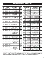
Page 19: ...at Plate Bevel 1 93 AT6535 093 Warning Label 1 94 AT6535 094 Plastic Base 1 95 AT6535 095 1 2 Upper Washer 1 96 AT6535 096 3 4 Upper Washer 1 97 AT6535 097 1 Upper Washer 1 98 AT6535 098 1 1 2 Upper Washer 1 99 AT6535 099 Spindle Nut Wrench 1 100 AT6535 100 Switch Retainer Plate 1 101 AT6535 101 Switch Locating Piece Lower 1 102 AT6535 102 ON OFF Switch 1 103 AT6535 103 Switch Locating Piece Upper...

Page 20: ...he product must be shipped in its original container or an equivalent properly packed to withstand the hazards of shipment The product must be fully insured with a copy of the warranty card and or the proof of purchase enclosed There must also be a description of the problem in order to help our repairs department diagnose and fix the issue Repairs will be made and the product will be returned and...

Reviews: