background image


PEGASUS Operating and Service Manual 

Wentworth


Laboratories


3.2 

Fixed Pegasus Probe Height Adjustment 

Ensure the 

Pegasus Probe

 connector is plugged in to number one edge sensor socket at the 

rear of the prober, and a needle has been placed in the needle holder 

Run the Probe Height facility on the prober to set the Gross and Fine heights. 

Should it be required, the platform can be raised and lowered using the Platform adjusting 
micrometer at the rear of the prober. 

Platform Height Adjustment 


Fig.3 Platform height adjustment 

The best electrical isolation is achieved when the probe holder is 4.5mm from the 
substrate.  


Probe Holder

Chuck Plate

4.5mm

Figure 4. Optimum Working Distance Setting 


Summary of Contents for Pegasus S200

Page 1: ...Wentworth Laboratories Pegasus Probe Installation and Operation Issue 2 0 December 2003 The Leader in ProbeAbility...

Page 2: ......

Page 3: ...ake changes to the specifications of the products described within at any time without notice and without obligation to notify any person for such revision or change Contact Information If you have an...

Page 4: ......

Page 5: ...be The position of this probe will be set prior to shipment such that the nominal position of the needle will be coincident with the chuck centre when the prober is first initialised Whilst it is poss...

Page 6: ...the amount of probe force required to break the edge sense contact can be adjusted Replacement of the probe needle is quick and easily achieved without the requirement for adhesives or any special too...

Page 7: ...e needle Optional 45 or 60 probe to substrate orientation Adjustable Pegasus Probe Adjustment Radial 12mm coarse 5mm fine Tangential 5mm Height 10mm Probe Needle Size 0 5mm diameter 0 020 Probe Force...

Page 8: ...mbwheel Note The position of the fixed probe will have been set prior to shipment Vertical Thumbwheel Locking Screw Mounting Screws Fig 2 Mounting the fixed Pegasus Probe 3 1 Fixed Probe Setting Proce...

Page 9: ...needle holder Run the Probe Height facility on the prober to set the Gross and Fine heights Should it be required the platform can be raised and lowered using the Platform adjusting micrometer at the...

Page 10: ...the probe height routine and raise the chuck until it comes into contact with the Fixed Pegasus Probe Using the vertical thumbwheel lower each Adjustable Pegasus Probe until an X appears on the scree...

Page 11: ...directly to the connector provided on the side of the Pegasus Probe body and anchored to the side of the body as shown Connecting the tester cable directly to the needle can influence the performance...

Page 12: ...th Laboratories Fig 7 Cable Management Clamps Cable clamps are provided on the underside of both sides of the platform to guide the tester and edge sense cables to the rear of the prober Fig 7 8 Fig 8...

Page 13: ...e holder by pulling the sprung loaded clamp back towards the Pegasus Probe body Fig 9 and inserting the needle through the exposed hole from the underside This operation can be performed with the Pega...

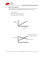
Page 14: ...the S200 and Pegasus Probe configuration to obtain the desired probe mark throughput conditions These are listed below Probe Contact Force S200 Contact Enhancement Parameter S200 Damping Enhancement P...

Page 15: ...y rotating this screw either clockwise or counter clockwise will increase or decrease the contact force The direction required can be obtained by stepping 1 or 2 devices after adjustment and observing...

Reviews: