Anhang / Appendix / Annexes
20
0102
Updated: 16.08.2004
Page 1 of 2
This document is produced electronically and is legally binding, even without an original signature.
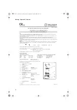
Operation and assembly instructions for cable and line glands
“Increased safety – E Ex “e” ignition protection level
Product ref.: U 2. UNI E Ex e, nickel-plated brass
Use
“U 2. UNI E Ex e” cable and line glands are used for inserting permanently laid cables and lines into the connection room or casing of explosion-
proof electrical equipment belonging to device group II and to categories 2 G/D and 3 G/D.
The connection room or casing must meet the “Increased safety – E Ex “e” ignition protection level according to EN Standards EN 50014:1992, EN
50019:1994 and EN 50281-1-1:1998.
The cable and line gland is suitable for equipment classified as having a “high” degree of mechanical danger according to EN 50014.
When selecting the material of the sealing inserts, the environment as well as surface and operation temperatures at the installation site must be taken
into account.
If the cable glands are properly fitted, it is possible to comply with IP 68 protection level according to IEC 529 or EN 60529. The minimum protection
level required for connection rooms (IP 54) are met in any case.
Marking
The “U 2. UNI E Ex e” cable glands comply with standards EN 50014:1992, EN 50019:1994 and EN 50281-1-1:1998. They were subjected to an EU
design test according to EU-Directive 94/9/ EC by the “Physikalisch - Technische Bundesanstalt” (German national physical-technical institute).
They are thus marked as follows:
II 2 G/D
E Ex e II
PTB 98 ATEX 3109
IP 68
XX
and are also marked with the connection thread type and size, e.g. M 16 or PG 21.
N.B.: In accordance with EU-directive 94/9/ EG, CE marking does not apply to components.
The sealing inserts made from
PVC are colour-coded depending on sealing use according to
Table 1
.
LSR are transparent,
TPE - V are a natural grey/beige colour.
The maximum diameter for the line to be inserted is specified on the sealing insert.
Cable and line gland range
with three different sealing inserts:
with two different connection threads and connection thread lengths:
Version
Material
Temperature
range
Connection thread
Connection thread length
Standard
PVC
- 20° C - + 85° C
Pg - thread DIN 46320
according to DIN 46320
Extreme
LSR
- 60° C - + 180° C
ISO-thread EN 60423
according to DIN 46319
UV
TPE - V
- 40° C - + 135° C
Pg / ISO-thread
15 mm long
with two different pressure nuts:
Standard – pressure screw
Pressure screw with strain relief
The standard pressure screw can be exchanged for a pressure nut with strain relief.
The sealing inserts are interchangeable.
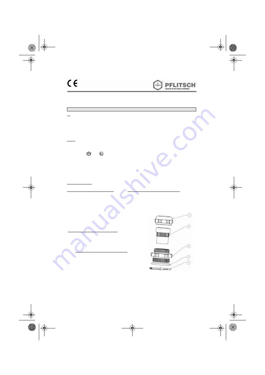
1. Pressure
screws
(brass, nickel-plated)
1.1 Standard
1.2
With strain relief device
2. Sealing
insert
Material
Sealing range
2.1
PVC, LSR and TPE-V
according to colour-code
2.2
PVC and TPE-V (multi) max. cable diameter
2.3 PVC
(flat)
2.4
Dummy sealing insert (accessories)
2:5
Closed sealing insert (accessories)
3. Double
nipple
(nickel-plated brass)
Connection thread
Connection thread length
3.1
Pg - thread
DIN 46320
3.2
ISO-thread EN 60423
according to DIN 46319 (reduced;
expanded)
3.3
Pg / ISO-thread
15 mm long
4.
Connection thread sealing ring
4.1
Material:
buna N ( black )
LSR
(
red
)
PE
(transparent)
5.
Counter-nut (accessories)
5.1
Material:
nickel-plated
brass
1 ) Comment:
310_761_003_0305_A5.fm Seite 20 Mittwoch, 16. März 2005 4:35 16


