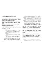
a) Leave the test lead at " S 4 " (as if you tested the
M/Man stops)
b) Depress the button "Orchestra Coupler" (right control
panel)
c) Depress the tab " Horn 8" of the upper manual d)
Mate the connector attached to branch 9.4 with plug
2 of the U /Man I fixed stops, referring to Fig. 88.
You should be able to hear that stop from your speaker. If you
don't, well, you still have to trace the signal using the descriptions at
the beginning of this chapter.
Compare the sounds of the U/Man II fixed stops with the
descriptions below. Remember, while the tab switches are located
on the U /Man I voicing block, you are listening to the circuitry on
the U/Man ll block (without switches).
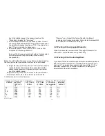
Sound Characteristics of the U /Man Fixed Stops (applies to
U/Man land U/Man ll)
1. Horn 16'(or Flugel horn 16')
Subdued "brassy'; a bit hollow at the bass end.
2. Saxophone 16'
Rich in harmonics with traces of a "stopped" pipe at middle to low
pitches, very reed-like.
3. Accordion 16'
Very brilliant with lots of harmonics (contains the aliquotes 1-3/5'
and 1-1/3'respectively).
4. Trombone 16'
Bold and "brassy".
5. Cello 16'
Plenty of harmonics, but with a warm character.
6. Clarinet 8'
Pitched one octave above the 16' stops, typical hollow woodwind
sound.
7. Horn 8'
Fundamental tone somewhat suppressed, barely nasal character.
8. Schalmei 8'
Rich in harmonics with a mellow touch, becomes slightly hollow at
the bass end.
9. Trumpet 8'
Loud metallic sound with high pitched resonance.
10. Viola 8'
Brighter than the lower pitched cello 16:
11. Tibia (Flute) 4'
Pitched one octave above the 8' stops, mellow and "airy".
12. Violin 4'
Very bright, little fundamental tone.
13. Diapason (Principal) 2'
Pitched one octave higher than the 4' stops, full 5.
sound with plenty of harmonics.
14. Cymbal ll
Very piercing, glittering all the way down to the bass end.
15. Mixture V
AM 075 (Part)
18
Summary of Contents for GALAXY
Page 1: ...Master Assembly GALAXY AM 075 AM 075 Part 1 ...
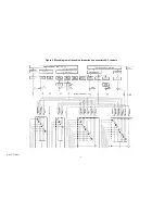
Page 4: ...Figure 1 Layout of the building blocks in the organ top AM 075 Part 4 ...
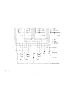
Page 5: ...Figure 2 Block diagram of the audio distribution and associated DC controls AM 075 Part 5 ...
Page 6: ...AM 075 Part 6 ...
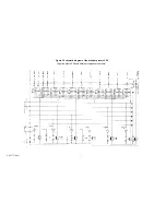
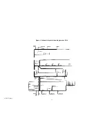
Page 33: ...Figure 4 Schematic layout of the wiring harness GO 4 AM 075 Part 33 ...


