ALLACCIAMENTO DELL’ IMPIANTO ELETTRICO
I
ATTENZIONE
Le operazioni sottoelencate devono essere ese-
guite da personale qualificato.
1) Prima del collegamento elettrico verificare che :
·
l’impianto di alimentazione al sollevatore sia dotato delle prote-
zioni previste dalle Norme Vigenti nel paese in cui lo stesso vie-
ne installato.
·
la linea di alimentazione abbia la seguente sezione :
Tensione sollevatore 400V trifase: ............minimo 2,5 mm2
Tensione sollevatore 230V trifase: ............minimo
4 mm2
Tensione sollevatore 230V monofase: ......minimo
6 mm2
·
le oscillazioni di tensione rientrino nel campo di tolleranza previ-
sto dalle specifiche.
Prevedere protezione da 10A per funzionamento trifase e 16A
per funzionamento monofase.
2) Eseguire i seguenti collegamenti al quadro di comando seguen-
do gli schemi delle pag.10 e 11(Vedere anche Fig.49):
·
collegamento microinterruttori di fine corsa;
·
completare l’ allacciamento dell’ elettrovalvola posta sulla cen-
tralina idraulica;
·
collegare gli elettromagneti; il cavo che va all’ elettromagnete
posto sulla colonna lato servizio, corre parallelamente al tubo
del circuito idraulico;
·
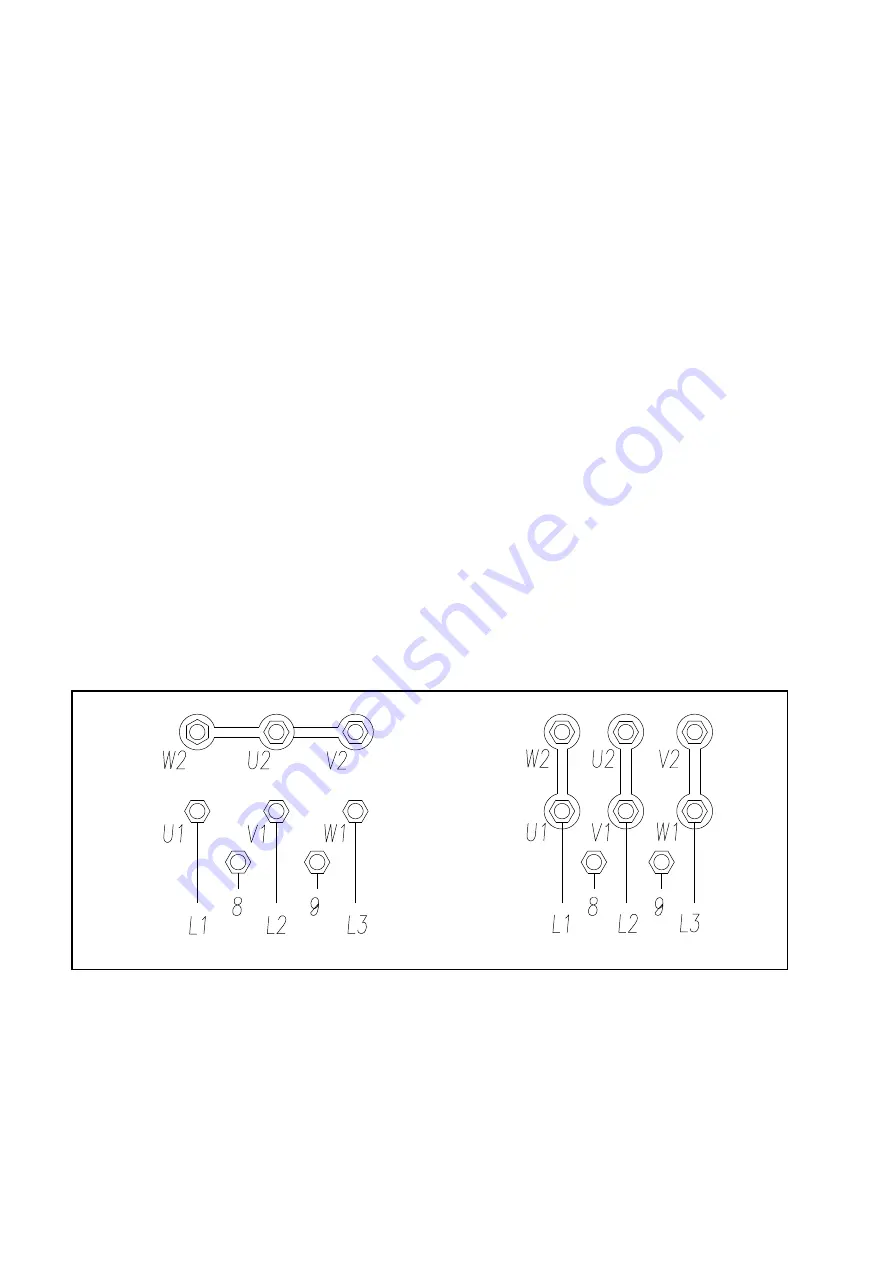
collegare il motore elettrico: aprire la scatola dei contatti posta
sullo stesso ed effettuare i collegamenti come indicato in Fig.48
in funzione della tensione a cui verrà alimentato il sollevatore.
·
collegare la protezione termica (Rif. 8-9 Fig.48).
I
l quadro elettrico viene predisposto dal costruttore per il fun-
zionamento a 400V trifase, pertanto se si desidera far funzio-
nare il ponte a 230V trifase, occorre cambiare il collegamento
sul trasformatore (vedere morsettiera sul trasformatore stes-
so).
3) Montare i carters di protezione magneti (Rif.6 Fig.46) con viti TE
M6x10.
Fig.48 Collegamenti motore e trasformatore
ELECTRIC PLANT CONNECTION
I
WARNING
The operations listed below must be performed
by skilled personnel.
1) Before connecting the electric system, make sure that:
·
the power supply plant to the lift is equipped with the protection
devices required by current standards in the country where the
machinery is installed.
·
the power supply line has the following cross-section:
Lift voltage 400V, three-phase ..................minimum 2.5 mm2
Lift voltage 230V, three-phase ..................minimum 4 mm2
Lift voltage 230V, single-phase .................minimum 6 mm2
·
the voltage oscillations are within the tolerance range set forth
by the specifications.
Provide protection from 10A for three-phase operation and
16A for singe-phase operation.
2) Connect the power and control system to the terminal strip on
the control box as shown in fig.49 ref. “A”, inserting the cable into
the rack passing through the prepared hole and following the wi-
ring diagram on pages 10 or 11.
·
limitswitches connection
·
complete the solenoid valve (on the hydraulic unit) connection.
·
connect the electromagnets; the wire coming towards the elec-
tromagnet on the service side post, is parallel to the hydraulic
circuit pipe.
·
connect the electric motor: open the contact box on the motor
itself and connect as shown in fig. 48, depending on voltage
used for the lift.
·
connected the temperature protection (Ref. 8-9 Fig. 48).
The electric panels are arranged by the manufacturer for ope-
rating at 400 V, three-phase: therefore, if you wish the lift to
operate at 230 V, three-phase, change the connection on the
transformer (see terminal board of the transformer).
3) Mount the magnet (ref.6, fig.46) protecting guards with HH
screws M6x10.
Fig.48
Motor and transformer connections
27
400V
230V
Summary of Contents for 208I/A
Page 1: ...I SOLLEVATORE ELETTROIDRAULICO A 2 COLONNE GB 2 POST ELECTRO HYDRAULIC LIFT 208I A...
Page 2: ......
Page 39: ...COLONNE E TRAVE SUPERIORE POSTS AND UPPER BEAM 39...
Page 40: ...CARRELLI E BRACCI CARRIAGES AND ARMS 40...
Page 41: ...SICUREZZE SAFETY DEVICES 41...
Page 42: ...QUADRO ELETTRICO TRIFASE THREE PHASE CONTROL PANEL 42...


