4) Eseguire l’allacciamento di potenza e di comando alla morsettie-
ra del quadro, come indicato in fig.49 rif. “A”, inserendo il cavo nel-
la cassetta passando dal foro predisposto e seguendo lo schema
dell’impianto elettrico come nelle pagine 10 e 11.
Fig.49 Collegamenti elettrici del quadro
5) Chiudere il coperchio del quadro elettrico, ruotare l’interrutore
generale (QS, Fig.50) in posizione I, premere il pulsante di salita
(rif. SB1, Fig.50) e, nel caso che, al contrario, abbia inizio la disce-
sa dei carrelli, invertire tra loro 2 fasi dell’alimentazione.
Il senso di rotazione del motore deve essere infatti lo stesso indi-
cato dalla freccia sulla pompa.
ATTENZIONE: una prolungata rotazione della pompa in senso
errato può creare gravi danni alla stessa.
6) Controllare il corretto funzionamento dei finecorsa di estremità
colonna azionandoli manualmente.
Fig.50
4) Complete the voltage and command connections to the control
panel clamp box as shown in fig.49, ref.A. Insert the wire in the box
through the pre-drilled drill, follow the wiring diagram as in pages
10 and 11.
Fig.49
Control panel electric connections
5) Close the cover of the electric box, turn the main switch (QS,
Fig.50) to position 1, press the up push button (ref. SB1, Fig.49)
and, if the carriage goes down, reverse the 2 power supply phases.
The direction of motor rotation should be the one shown by the ar-
row on the pump.
BEWARE: The pump rotating for a long time in the wrong
direction, may cause itself serious damages.
6) Make sure that the post end limit switches work properly by
pressing them manually.
28
SB1
QS
MAGNETE LATO COMANDO / COMMAND SIDE MAGNET
MAGNETE LATO SERVIZIO / SERVICE SIDE MAGNET
ELETTROVALVOLA SU CENTRALINA / SOLENOID VALVE ON POWER UNIT
MOTORE / MOTOR
MICROINTERRUTTORE DI SALITA / RAISE LIMIT SWITCH
“A”
MICROINTERRUTTORE FUNI / CABLE SWITCH
MICROINTERRUTTORE DISCESA (QM11) / DESCENT LIMIT SWITCH (QM11)
MORSETTIERA /
CLAMP
7
Azzurro
Blue sky
16
Nero
Black
17
Marron
Brown
18
Grigio
Grey
NC
NO
21
22
13
14
QM11
Summary of Contents for 208I/A
Page 1: ...I SOLLEVATORE ELETTROIDRAULICO A 2 COLONNE GB 2 POST ELECTRO HYDRAULIC LIFT 208I A...
Page 2: ......
Page 39: ...COLONNE E TRAVE SUPERIORE POSTS AND UPPER BEAM 39...
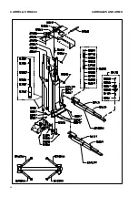
Page 40: ...CARRELLI E BRACCI CARRIAGES AND ARMS 40...
Page 41: ...SICUREZZE SAFETY DEVICES 41...
Page 42: ...QUADRO ELETTRICO TRIFASE THREE PHASE CONTROL PANEL 42...


