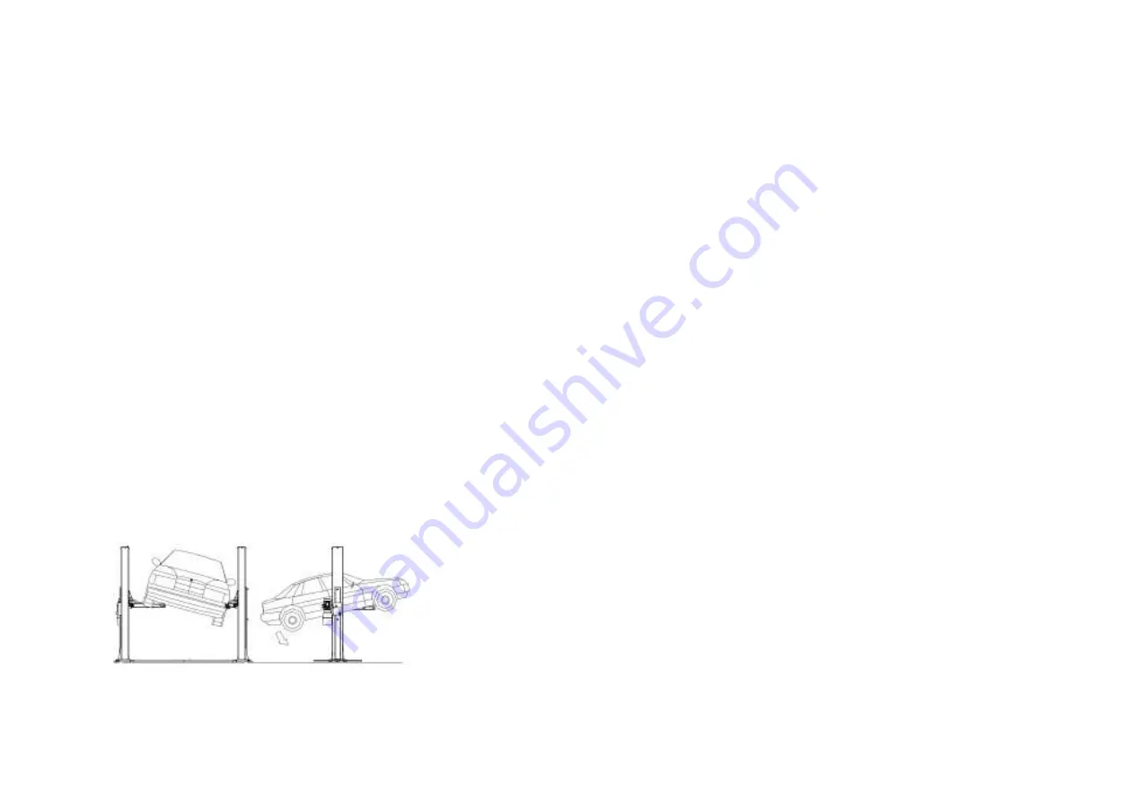
Fig.13 Abb.13
PRECAUZIONI GENERALI
L'operatore e il meccanico riparatore devono attenersi alle pre-
scrizioni della legislazione relativa alla prevenzione degli inciden-
ti, in vigore nel paese di installazione del sollevatore.
Inoltre, l'operatore e il meccanico riparatore devono:
1.Lavorare sempre nell'area di lavoro programmata come mo-
strato sul manuale.
2.In nessun caso rimuovere o disattivare le protezioni e i disposi-
tivi di sicurezza meccanici, elettrici o di altro tipo.
3.Leggere gli avvisi di sicurezza affissi sulla macchina e le infor-
mazioni sulla sicurezza in questo manuale.
Nel manuale tutti gli avvisi di sicurezza vengono indicatii come segue:
PERICOLO
: indica pericolo imminente che può causare seri
danni o morte.
AVVISO
: indica situazioni e/o tipi di manovre non sicuri e che
possono causare lesioni di varie entità o morte.
ATTENZIONE
: indica situazioni e/o tipi di manovre non sicuri e
che possono causare lesioni minori alle persone e/o danneggiare
il sollevatore, il veicolo o altre proprietà.
RISCHI DI FOLGORAZIONE
Avvisi di sicurezza specifici devono essere affissi al sollevatore nelle
aree in cui il rischio di folgorazione è particolarmente elevato.
RISCHI E DISPOSITIVI DI PROTEZIONE
Esamineremo ora i rischi a cui l'operatore e il meccanico ripara-
tore possono essere esposti con il veicolo immobilizzato in posi-
zione elevata e insieme ai dispositivi di protezione adottati dal
costruttore per ridurre tali rischi al minimo.
MOVIMENTO LONGITUDINALE E LATERALE
Per movimento longitudinale si intende lo spostamento in avanti
e indietro del carico.
Il movimento laterale implica lo spostamento verso destra e verso si-
nistra del veicolo, specialmente durante la fase di sollevamento.
Tali movimenti possono essere evitati posizionando correttamen-
te il veicolo sui piattelli in gomma posti sui bracci i quali devono
essere precedentemente regolate alla stessa altezza del veicolo.
Non spostare il veicolo dai bracci né regolare i bracci e i piattelli fino a
che il sollevatore non è posizionato all'altezza minima ; in tale posizio-
ne i bracci e i piattelli non hanno alcun contatto con il veicolo.
GENERAL PRECAUTIONS
The operator and the maintenance fitter are required to observe the
prescriptions of accident prevention legislation in force in the country
of installation of the lift.
Furthermore, the operator and the maintenance fitter must:
1. Always work in the scheduled working area as shown in the ma-
nual
2. Never remove deactivate the guards and mechanical, electri-
cal, or other types of safety devices.
3. Read the safety notices affixed to the machine and the safety
information in this manual.
In the manual all safety notices are shown as follows:
DANGER
: indicates imminent danger that can result in serious
injury or death.
WARNING
: indicates situations and /or types of maneuvers that
are unsafe and can cause injuries of various degrees or death.
CAUTION
: indicates situations and /or types of maneuvers that
are unsafe and can cause minor injury to persons and /or dama-
ge the lift, the vehicle or other psaltery.
RISKS OF ELECTRIC SHOCK:
Specific safety notice affixed to the lift in areas where the risk of
electric shock is particularly high.
RISKS AND PROTECTION DEVICES
We shall now examine the risks to which the operator and the mainte-
nance fitters may be exposed when the vehicle is immobilized in the
raised position, together with the protection devices and adopted by
the manufacture to reduce all such hazards to the minimum.
LONGITUDINAL AND LATERAL MOVEMENT
Longitudinal movement is considered the backward and forward
shifting of the load.
Lateral movement implies the shifting to the left or right of the ve-
hicle, especially during the lifting phase on the rack.
These movements can be avoided by positioning the vehicle correctly
on the arm disk support plates, which must be previously adjusted to
the same height (by loosening or tightening) as the vehicle.
Do not move the vehicle in relation to the arms or adjust arms and
disk support plates until the arms have been totally lowered, i.e. the
disk support plates must be free from all contact with the vehicle.
23
Summary of Contents for 209I/B
Page 2: ......
Page 61: ......
Page 62: ...STRUTTURA PRINCICPALE 380 MAIN STRUCTURE 380V ...
Page 63: ...COLONNA COMANDO 380 MAIN COLUMN 380V ...
Page 64: ...QUADRO ELETTRICO TRIFASE 380V THREE PHASE CONTROL PANEL 380V ...
Page 65: ...CENTRALINA OLEODINAMICA 380V OLEODYNAMIC CONTROL UNIT 380V ...
Page 66: ...STRUTTURA PRINCICPALE 220 MAIN STRUCTURE 220V ...
Page 67: ...COLONNA COMANDO 220 MAIN COLUMN 220V ...
Page 68: ...QUADRO ELETTRICO MONOFASE 220V MONO PHASE CONTROL PANEL 220V ...
Page 69: ...CENTRALINA OLEODINAMICA 220V OLEODYNAMIC CONTROL UNIT 220V ...
Page 70: ...BASAMENTO CHASSIS ...
Page 71: ...CILINDRO CYLINDER ...
Page 72: ...CARRELLO PRINCIPALE MAIN CARRIAGE ...
Page 73: ...CARRELLO SECONDARIO SUB CARRIAGE ...
Page 74: ...BRACCIO LUNGO LONG ARM BRACCIO CORTO SHORT ARM ...
Page 76: ...COLONNA SERVIZIO SUB COLUMN ...


