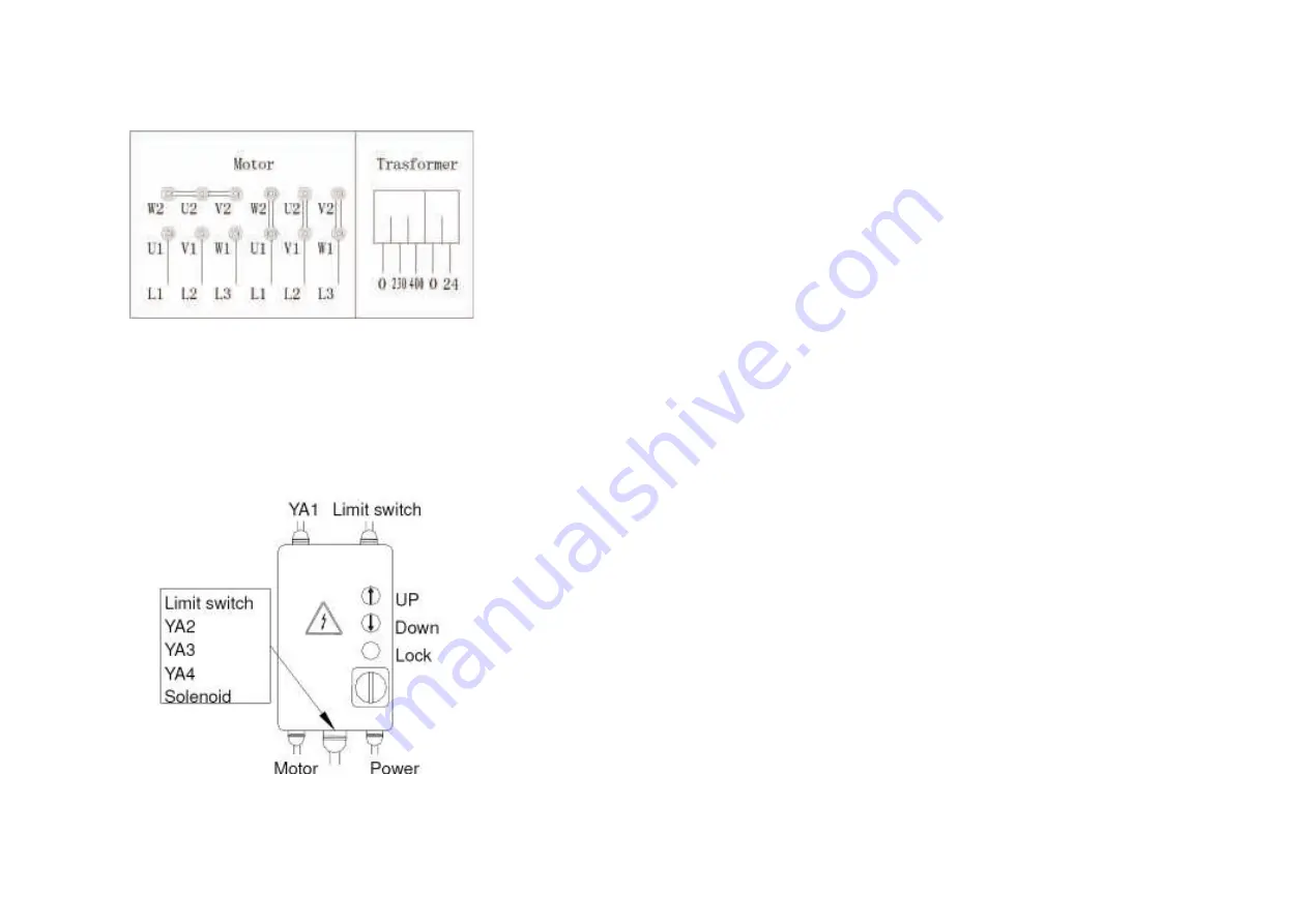
Fig.39 Abb.39
Fig.40 Abb.40
CONNESSIONE DELL'IMPIANTO ELETTRICO
I
AVVISO
Le operazioni elencate qui di seguito devono essere effettuate
da personale esperto.
1)Prima di connettere il sistema elettrico, assicurarsi che:
1.L'impianto elettrico fornito con il sollevatore sia equipaggiato
con il dispositivo di protezione richiesto dagli standard correnti
del paese dove la macchina viene installata.
2.La linea di alimentazione elettrica ha le seguenti sezioni trasversali:
Voltaggio del sollevatore 400V, trifase….........…minimo 2,5mm2
Voltaggio del sollevatore 230V, trifase……………minimo 4mm2
Voltaggio del sollevatore 230V, monofase………..minimo 6mm2
3.Le oscillazioni del voltaggio rientrano nella gamma di tolleranza
fornita dalle specifiche.
Il produttore fornisce il sollevatore per funzionare a 400V con
una configurazione trifase; se il voltaggio della linea è differente,
il motore e la connessione a trasformatore vanno cambiati
(fig.39); è inoltre necessario sostituire il relè termico richiedendo
tale parte al costruttore e/o al centro assistenza.
2)Connettere l'alimentazione e il sistema di controllo alla morsettiera
sul quadro di controllo (fig.40) inserendo il cavo nella struttura pas-
sando per il foro predisposto e seguendo lo schema del cablaggio a
pagina 13.
1.Installare il quadro elettrico sulla colonna principale.
2.Connettere gli interruttori di fine corsa.
3.Completare la connessione della valvola a solenoide (sull'unità
idraulica).
4.Connettere gli elettromagneti.
5.Connettere il motore elettrico.
6.Completare le connessioni di alimentazione alla morsettiera
del pannello di comando.
3)Chiudere il coperchio del quadro elettrico, ruotare l'interruttore
principale nella posizione 1, premere il pulsante di sollevamento
(fig.40); il verso di rotazione del motore dovrebbe essere quello
mostrato dalla freccia sulla pompa.
I
ATTENZIONE: Se la pompa ruota
a lungo nel verso sbagliato può
subire seri danni.
4)Accertarsi che i finecorsa di estremità nelle colonne funzionino
appropriatamente premendoli manualmente
ELECTRIC PLANT CONNECTION
I
WARNING
The operations listed below must be performed by skilled personnel
1) Before connecting the electric system, make sure that:
1. The power supply plant to the lift is equipped with the protec-
tion device required by current standards in the country where
the machinery is installed.
2. The power supply line has the following cross-section:
Lift voltage 400V, three-phase………............…minimum 2.5mm2
Lift voltage 230V, three-phase……………………minimum 4mm2
Lift voltage 230V, single-phase……………………minimum 6mm2
3. The voltage oscillations are within the tolerance range set forth
by the specifications.
The manufacturer supplies the rack to operate at 400V with a
three-phase configuration; if the line voltage is different, the mo-
tor and transformer connection must be changed (Fig.39) it is
also necessary to replace the thermal relay requesting that part
from the manufacture and/or service center.
2) Connect the power and control system to the terminal strip on the
control box(Fig.40), inserting the cable into the rack passing through
the prepared hole and following the wiring diagram on pages 13.
1. Install the electric box on the main column.
2. Connection the limit switches.
3. Complete the solenoid valve (on the hydraulic unit) connection.
4. Connection the electromagnets.
5. Connect the electric motor.
6. Complete the voltage and command connections to the control pa-
nel clamp box.
3) Close the cover of the electric box, turn the main switch to po-
sition 1, press the up push button (Fig.40) ,The motor rotation
wise should be the one shown by the arrow on the pump
I
BEWARE: The pump rotating for a
long time in the wrong sense may
cause itself serious damages.
4) Make sure that the post end limit switches work properly by
pressing them manually..
38
Summary of Contents for 209I/B
Page 2: ......
Page 61: ......
Page 62: ...STRUTTURA PRINCICPALE 380 MAIN STRUCTURE 380V ...
Page 63: ...COLONNA COMANDO 380 MAIN COLUMN 380V ...
Page 64: ...QUADRO ELETTRICO TRIFASE 380V THREE PHASE CONTROL PANEL 380V ...
Page 65: ...CENTRALINA OLEODINAMICA 380V OLEODYNAMIC CONTROL UNIT 380V ...
Page 66: ...STRUTTURA PRINCICPALE 220 MAIN STRUCTURE 220V ...
Page 67: ...COLONNA COMANDO 220 MAIN COLUMN 220V ...
Page 68: ...QUADRO ELETTRICO MONOFASE 220V MONO PHASE CONTROL PANEL 220V ...
Page 69: ...CENTRALINA OLEODINAMICA 220V OLEODYNAMIC CONTROL UNIT 220V ...
Page 70: ...BASAMENTO CHASSIS ...
Page 71: ...CILINDRO CYLINDER ...
Page 72: ...CARRELLO PRINCIPALE MAIN CARRIAGE ...
Page 73: ...CARRELLO SECONDARIO SUB CARRIAGE ...
Page 74: ...BRACCIO LUNGO LONG ARM BRACCIO CORTO SHORT ARM ...
Page 76: ...COLONNA SERVIZIO SUB COLUMN ...


