


PAVIMENTO
Il sollevatore deve essere installato su platea orizzontale di spes-
sore minimo 150 mm (Fig.34) realizzata in calcestruzzo dosato con
resistenza min di 25 N/mm2.
Il pavimento deve inoltre essere piano e ben livellato (10 mm di tol-
leranza sul livellamento).
Nel caso di applicazioni particolari, interpellare il costruttore.
MONTAGGIO
I
ATTENZIONE
DURANTE IL MONTAGGIO NON É AMMESSO
NESSUN ESTRANEO AI LAVORI
Per effettuare l’ installazione del sollevatore,considerati i pesi
dei vari componenti, é necessario provvedere ad un mezzo di
sollevamento con le seguenti caratteristiche:
Portata minima: 300 kg.
Altezza massima di sollevamento: 4 m
Prima di iniziare il montaggio verificare,con
il Packing List, che nella gabbia sia conte-
nuto tutto il materiale necessario.
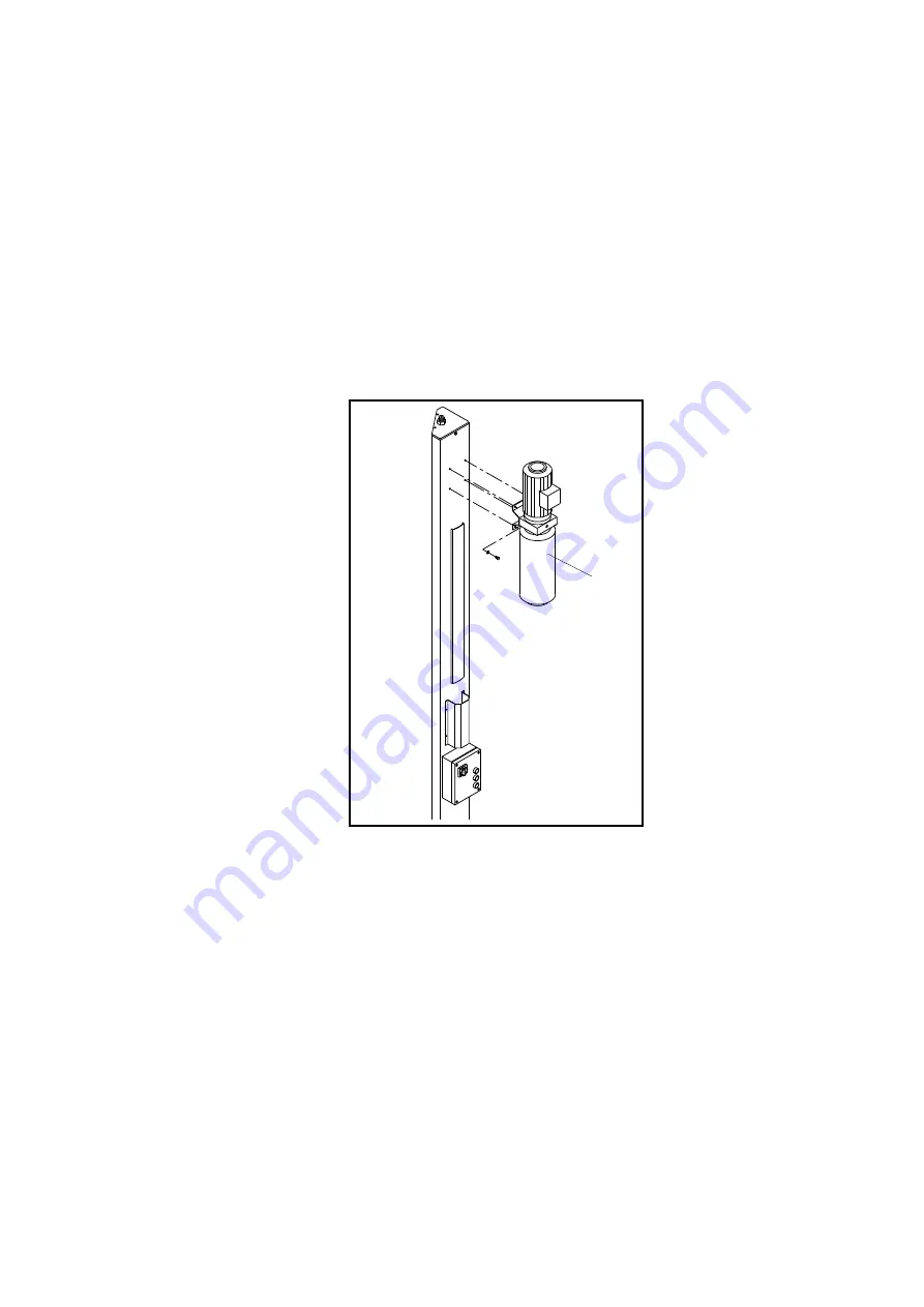
MONTAGGIO COLONNE
1 - Prendere con il mezzo di sollevamento
la colonna comando e, in posizione oriz-
zontale, montare la centralina idraulica
(priva di olio) (Rif.1 Fig.33) utilizzando le 4
viti TE M8x16 con relative rondelle già pre-
montate nei fori allo scopo predisposti.
Fig.33
Montaggio centralina
FLOOR
The lift must be installed on a horizontal concrete bed with a mini-
mum thickness of 150mm (Fig.34) built and a resistance minimum
25 N/mm2.
The floor must also be flat and level (10 mm of tolerance for level-
ling).
Consult the manufacturer with regard to special applications.
ASSEMBLING
I
WARNING
DURING INSTALLATION ONLY AUTHORISED
PERSONNEL IS ALLOWED
To assemble the lift, the weight of the various parts is to be
considered, in order to provide a lifting machine with the
following caracteristics:
Minimum capacity300kg
max. lifting height 4 m
Before starting to assemble the lift,
check the crate contains all the
needed material.
POSTS ASSEMBLING
1 - With the lifting machine take the
command post and, in an horizon-
tal position, assemble the hydraulic
unit (without oil) (ref.1, fig.33) using
the 4 HH screws M8x16 and was-
hers, already set in the drills.
Fig. 33
Power unit assembling
22
1


