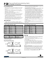
8 - Prendere la trave superiore, im-
bragandola con il mezzo di solleva-
mento, posizionarla alla sommità
delle colonne e fissarla alla piastra
superiore con le 4 viti TE M8x25 (1)
e alla colonna con le 4 viti TE
M8x20 (2) e con i dadi esagonali e
le rondelle piane (Fig.37).
9- Verificare il parallelismo e la per-
pendicolarità delle colonne e, se oc-
corre, dopo aver allentato quanto
basta le viti dei tasselli inserire la-
mierini di spessoramento di larghez-
za 80x80 mm in prossimità dei fori.
L’ operazione di spessoramento
deve essere la più ampia possibi-
le e sempre in prossimità dei fori
di fissaggio.
10- Fissare definitivamente le colon-
ne al pavimento, serrando le viti dei
tasselli con chiave dinamometrica
(Fig.38) con coppia di serraggio di
110 Nm, e la trave superiore alle
colonne.
Fig.38
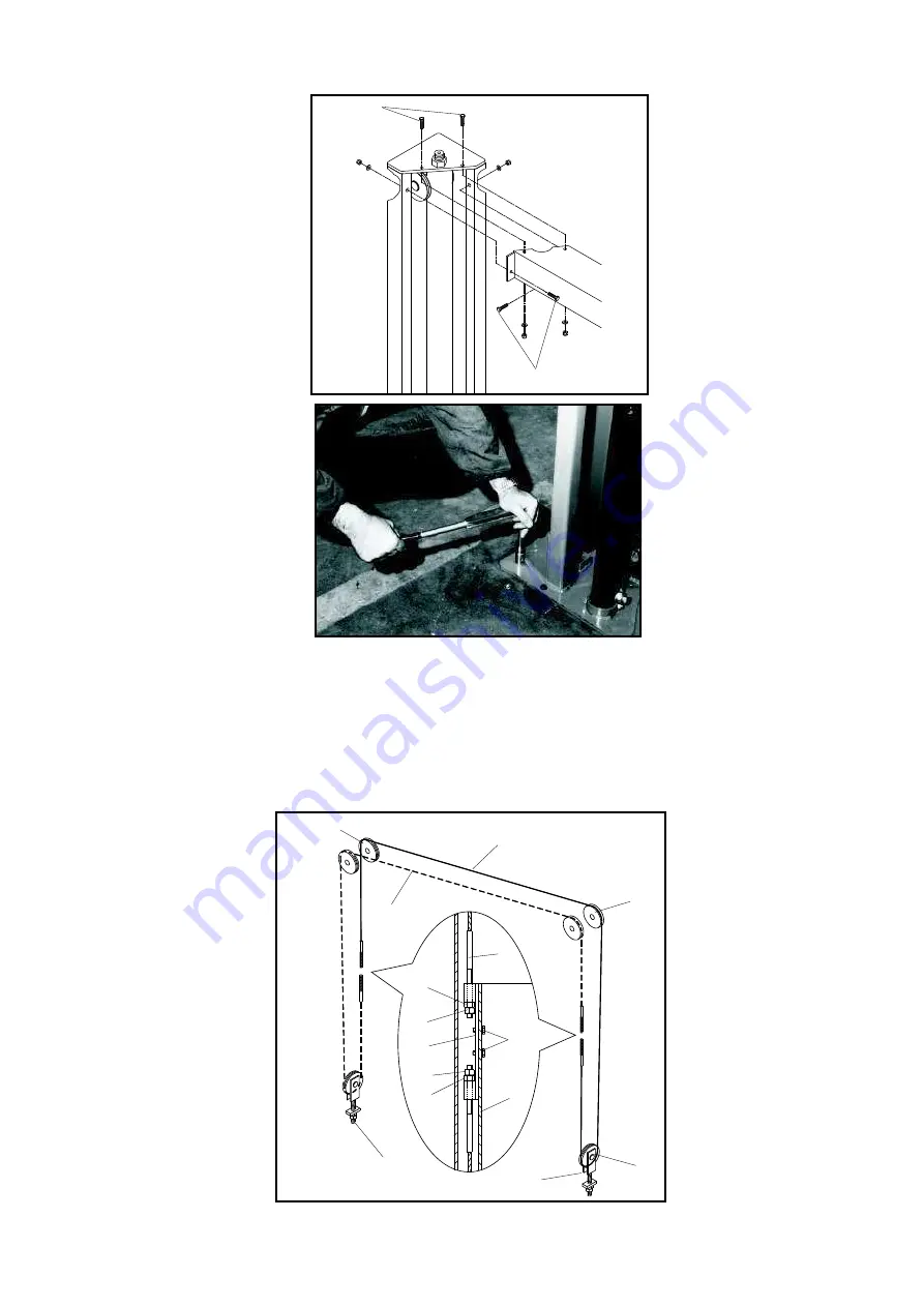
MONTAGGIO DELLE FUNI DI
SINCRONISMO (Fig. 39).
1 - Sollevare i due carrelli a 50÷60 cm da terra.
2 - Montare l’apposito attacco funi (1) ai due carrelli (2) con le due
viti TE M10x16 (3).
3 - Prelevare una fune (4) dal rotolo e infilarne, dall’ alto verso il
basso, l’estremità col tirante (5) nel foro superiore dell’apposito at-
tacco sul carrello lato servizio (1); quindi montare il dado (6) e il
controdado (7) sulla parte sporgente e bloccarli.
4 - Prendere l’ altra estremità e farla passare all’ interno della co-
lonna e poi nelle gole delle puleggie (8 e 9) poste nella parte supe-
riore della colonna; passando poi tra colonna e carrello lato co-
mando, avvolgerla per mez-
zo giro attorno alla puleggia
(10) montata nella parte in-
feriore della colonna e suc-
cessivamente infilarla nel
foro inferiore dell’ attacco
del carrello (1).
5 - Montare gli altri due dadi
sulla parte del tirante spor-
gente al di sopra dell’ attac-
co stesso e bloccarli.
6 - Eseguire le stesse ope-
razioni sull’ altro carrello con
la seconda fune (11).
7 - Mettere in tensione le
funi agendo su dado e con-
trodado (12) dei tiranti delle
puleggie inferiori (10). La re-
gistrazione va suddivisa in
modo equivalente sui quat-
tro terminali, verificando che
I carrelli siano livellati. Le
funi devono risultare molto
tese (effetto corda di chitar-
ra).
8 - Finita la registrazione
bloccare i controdadi (12).
Fig.39
Montaggio delle funi di
sincronismo
8 - Sling the upper beam with the
lifting unit, place it on top of the
posts and fix to the upper plate
with the 4 HH screws 8x25 (1) and
to the culomn with the 4 HH screws
8x20 (2) and with hex. nuts and the
flat washers (Fig.37).
9 - Posts must be perpendicular
and parallel. If needed, correct the-
ir position after having untightened
a little the bolts screws, insert thic-
kness pads (width 80x80mm) near
the drills.
Thickness pads should be as
much as possible and always
near the fixing drills
.
10 - Fix the posts once for all to the
basement, tightten the anchor bolts
with a torque wrench (110 Nm)
(Fig.38). Also fix the upper beam to
the posts.
ASSEMBLING THE
SYNCHRONOUS DEVICE
CABLES (Fig.39)
1- Lift the two carriages to 50÷60 cm from ground.
2- Mount the special support cables (1) to the two carriages (2)
with the two HH screws 10x16 (3).
3 - Take one cable (4) from the coil and put the threaded end (5) in
the upper drill of the special support on the service side carriage
(1). Mount nut (6)and counternut (7) on the protruding part and
block them.
4 - Take the other end and make it pass inside the post and into
the pulleys (8, 9) on the upper part of the column, passing then
through column and carriage side command. Wrap for half a spin
around the pulley (10) at bot-
tom of the post, then insert it
in the inferior drill on the plate
fixed to the carriage. (1)
5 - Fix the remaining two bolts
on the cable end protruding
from the plate and block them.
6 - The same operations are
to be made on the second
carriage with the other cable.
(11)
7 - Put the cables under ten-
sion operating the nut and co-
unternut (12) of the harness of
the inferior pulleys (10). The
adjustment should be done in
the same way on all four ter-
minals, checking that the car-
riages are levelled. The ca-
bles must be very tight (like a
guitar string).
8 - After adjustment lock the
counternuts (12).
Fig. 39 Mounting the synchronous
device steel cables.
24
8
4
11
9
5
6
7
3
4
5
10
12
12
1
2
Fig.37
1
2