


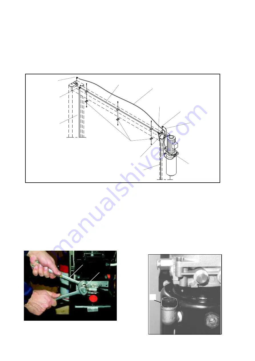
COMPLETAMENTO IMPIANTO IDRAULICO (Fig. 40).
1 - Collegare il tubo (1) all’ interno della trave superiore coi raccordi
(2 e 3) ai due tubi (5 e 6), premontati all’ interno delle colonne e
collegati, nella loro estremità, inferiore ai cilindri.
2 - Collegare la centralina all’ incrocio (3) del circuito mediante il
tubo (7).
I
ATTENZIONE
Tenere fermo il particolare 12 con una chiave (13) (Fig.40a).
Fig.40
3 - Montare all’estremità superiore dei cilindri i 2 raccordi a “L” (9)
forniti in dotazione, connettere ai due raccordi i tubi di scarico
Æ
8
(10) e collegarli al raccordo a “Y” (11) sulla centralina.
4 - Fissare il tubo (1) alla traversa con i tre collari (8) forniti in dota-
zione con le viti e i dadi.
5 - Serrare bene tutti i raccordi compresi quelli premontati presso il
costruttore.
6 - Riempire il serbatoio della centralina con 14 lt di olio idraulico
gradazione ISO 32 come IP HYDRUS OIL 32, SHELL TELLUS OIL
T32 o equivalenti (vedere Cap.2 Specifiche Tecniche).
7 - Togliere il tappo di carico olio e sostituirlo con il tappo di sfiato
fornito (Rif.1 Fig.41).
Fig.40a
HYDRAULIC PLANT (Fig.40)
1 - Connect the pipe (1) to the inside part of the upper beam, using
fittings 2 and 3 to the pipes 5 and 6. (already fixed inside the posts,
and connected, at bottom, to the cylinders)
2 - Connect the hydraulic unit to the circuit crossing (3) with a pipe
(7).
I
WARNING
Keep the detail 12 locked using a wrench (13) (Fig.40a).
3 - Fit the 2 "L" fittings (9) on the upper end of the cylinders, con-
nect the 2
Æ
8 exhaust pipes (10) to the 2 fittings and connect
them to the "Y" fitting (11) on the hydraulic unit.
4 - Fix the pipe (1) to the inside part of the upper beam with the
three collars (8) provided in endowment with the screws and the
nuts.
5 - Tighten all the fittings very well, even the one already mounted
by the manufacturer.
6 - Fill the Hydraulic unit tank with 14 litres of hydraulic oil ISO 32
as IP HYDRUS OIL 32, SHELL TELLUS OIL T32 or similar (See
Ch.2, Technical specifications).
7 - Remove the oil filling cap and replace it with the given drain cap
(Ref.1, fig.41).
Fig.41
25
5
1
2
9
6
7
8
3
10
9
10
11
1
13
12


