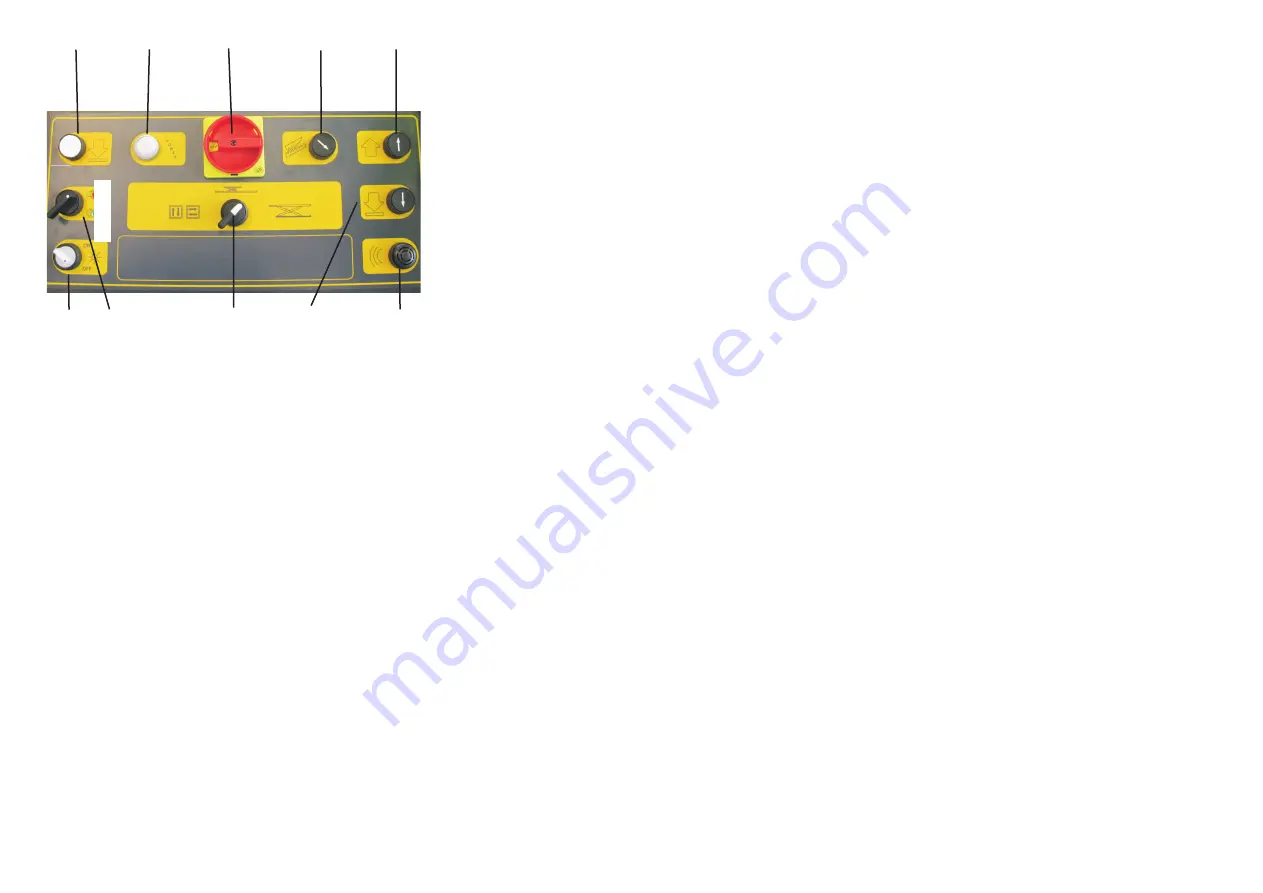
Fig.59-Abb.59
Fig.59 I comandi sulla consolle V5 - V6
SEQUENZA DI FUNZIONAMENTO
Prima di salire/scendere dal sollevatore, assicurarsi che le pedane
siano alla minima altezza.
Salire con l’ autovettura sul sollevatore a “ passo d’ uomo “,
posizionando la stessa correttamente .Spegnere il motore e innestare il
freno di stazionamento dopo aver posizionato l’ auotovettura sul ponte
sollevatore e ricordarsi di disinserire la leva del cambio posizionandola
sul “folle“.
SOLLEVAMENTO/DISCESA PEDANE:
Azionare i corrispondenti pulsanti salita/discesa.
Durante la discesa ad un’altezza di circa 500 mm. il sollevatore si ferma
per cui senza rilasciare il pulsante di discesa premere il pulsante di
autorizzazione; il dispositivo acustico inizia a suonare ed il sollevatore
si chiude completamente.
.
I
IMPORTANTE:
Durante i primi cicli di lavoro del sollevatore si possono verificare dei rumori
e/o dei cigolii, dovuti al non ancora avvenuto assestamento naturale delle
parti meccaniche. Questo inconveniente sparirà dopo aver eseguito qualche
altro ciclo di lavoro.
Fig.59 V5 - V6 controls on the board
OPERATING SEQUENCE
Make sure the platforms are at the minimum height before
lifting/lowering the car lift. Get on the vehicle and crawl on the car lift; be
sure the vehicle is centred and both rear and front wheels are properly
positionated.
Switch off the engine and engage the parking brake after placing the
vehicle on the car lift; furthermore disengage the shift lever and move it
to the “neutral” position.
PLATFORMS LIFTING/LOWERING:
Operate the corresponding lifting/lowering buttons .
In the lowering phase, the lift stops at an height of approx. 500 mm.
Therefore, without releasing the lowering button, press the enable
button. The acoustic alarm starts operating and the lift closed
completely.
I
IMPORTANT:
During the first operating cycles cracking noises could occur. This
trouble is only due to the natural settlement of mechanical parts, and
will soon disappear, after having carried out other operating cycles.es.
76
4
2
1
5
3
6
11
9
7
10
Summary of Contents for SATURNUS 40R
Page 2: ......
Page 23: ...21...
Page 27: ...Fig 14a Abb 14a Fig 14b Abb 14b 27...
Page 63: ...SCHEMA MONTAGGIO TUBAZIONI HYDRAULIC SCHEMA HYDRAULIK ESQUEMA V1 V2 Fig 44 Abb 44 61...
Page 92: ......
Page 93: ...BASE...
Page 94: ...PIANALE...
Page 95: ...TORRETTE...
Page 96: ...QUADRO DI COMANDO V1 CONTROL BOX STEUERTAFEL TABLEAU DE COMMANDE PANEL DE MANDO...
Page 97: ...QUADRO DI COMANDO V2 CONTROL BOX STEUERTAFEL TABLEAU DE COMMANDE PANEL DE MANDO...
Page 98: ...QUADRO DI COMANDO V3 CONTROL BOX STEUERTAFEL TABLEAU DE COMMANDE PANEL DE MANDO...
Page 99: ...QUADRO DI COMANDO V4 CONTROL BOX STEUERTAFEL TABLEAU DE COMMANDE PANEL DE MANDO...


