REV. 01 2013
18 / 24
x
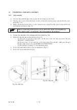
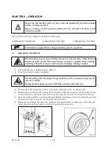
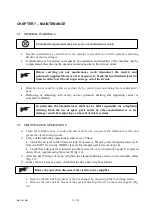
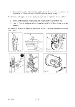
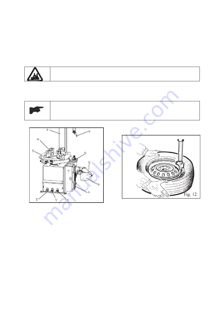
Move the tire so that the bead passes below the front section of the mounting head and is
brought up against the edge of the rear section of the mounting head itself.
x
Keeping the tire bead pressed down into the wheel rim channel with your hands, press down on
the pedal (Z) to rotate the turntable clockwise. Continue until you have covered the entire
circumference of the wheel rim (Fig. 12).
To prevent industrial accidents, keep hands and other parts of the body as far as
possible from the tool arm when the table top is turning.
x
Insert the inner tube if there is one and repeat the same operations to mount the upper side of
the tire.
Demounting and mounting are always done with the clockwise turntable
rotation. Anticlockwise rotation is used only to correct operator’s errors or if
the turntable stalls.
Fig. 11
Summary of Contents for TITANIUM BIKE
Page 2: ......
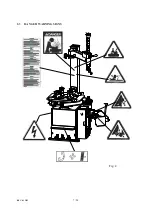
Page 9: ...REV 01 2013 7 24 2 3 DANGER WARNING SIGNS Fig 2 ...
Page 14: ...REV 01 2013 12 24 ...
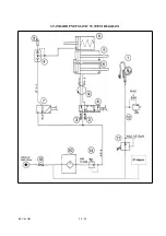
Page 26: ...REV 01 2013 24 24 STANDARD PNEUMATIC SYSTEM DIAGRAM ...
Page 27: ......
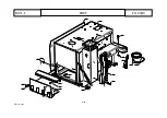
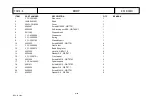
Page 28: ... 2 22 REV 01 2013 BODY TAV 1 1 ED 04 13 ...
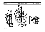
Page 30: ... 4 22 REV 01 2013 HORIZ AND VERT ARMS TAV 2 1 ED 04 13 ...
Page 33: ... 7 22 REV 01 2013 PEDAL BOX TAV 3 1 ED 04 13 ...
Page 37: ... 11 22 REV 01 2013 BEAD BREAKER TAV 4 1 ED 04 13 ...
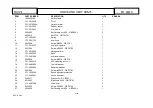
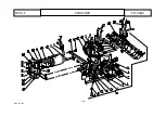
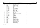
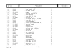
Page 40: ... 14 22 REV 01 2013 SELFͲCENTERING TURNTABLE TAV 5 1 ED 04 13 ...
Page 44: ... 18 22 REV 01 2013 3 MOTOR REDUCTION GEAR GROUP TAV 6 0 ED 04 13 ...
Page 47: ... 21 22 REV 01 2013 AIR LUBRICATOR GROUP TAV 8 1 ED 04 13 ...

