

3
/
22
REV. 01 2013
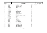
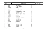
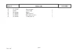
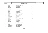
ITEM
PART NUMBER
DESCRIPTION
QTY
REMARK
1
YC1-3001800
Side cover
1
2
106B-2401001
Shell
1
3
202W-3018260
Cover
1
4
0202067
Screw M10X85 - GB/T70.1
1
5
0204005
Self-locking nut M10 - GB/T889.1
1
6
0511063
Grease brush
1
7
YC1-4299984
Grease cup
1
8
YC1-3000069
Spring
1
9
YC1-3002102
Wheel support
1
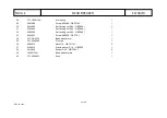
10
0202033
Screw M6X20 - GB/T70.1
4
11
YC1-3002099
Plastic foot
4
12
YC1-3006970
Bead lifting lever
1
13
0203029
Nut M8 - GB/T6170
2
14
0205008
Washer D.8 - GB/T97.1
2
15
YC1-3011970-1
Front panel
1
16
0201026
Screw M8X16 - GB/T5783
2
17
YC3-2412452-C
Pedal support
1
18
0201011
Screw M6X12 - GB/T5783
2
19
0205006
Washer D.6 - GB/T97.1
2
20
0202032
Screw M6X16 - GB/T70.1
5
21
0205007
Washer D.6 - GB/T96
9
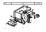
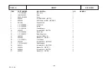
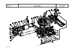
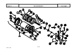
BODY
TAV.1.1
ED.
04/13
Summary of Contents for TITANIUM BIKE
Page 2: ......
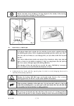
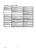
Page 9: ...REV 01 2013 7 24 2 3 DANGER WARNING SIGNS Fig 2 ...
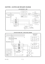
Page 14: ...REV 01 2013 12 24 ...
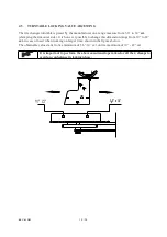
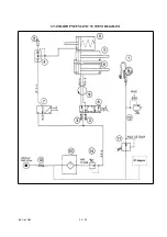
Page 26: ...REV 01 2013 24 24 STANDARD PNEUMATIC SYSTEM DIAGRAM ...
Page 27: ......
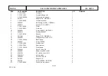
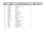
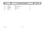
Page 28: ... 2 22 REV 01 2013 BODY TAV 1 1 ED 04 13 ...
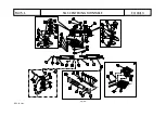
Page 30: ... 4 22 REV 01 2013 HORIZ AND VERT ARMS TAV 2 1 ED 04 13 ...
Page 33: ... 7 22 REV 01 2013 PEDAL BOX TAV 3 1 ED 04 13 ...
Page 37: ... 11 22 REV 01 2013 BEAD BREAKER TAV 4 1 ED 04 13 ...
Page 40: ... 14 22 REV 01 2013 SELFͲCENTERING TURNTABLE TAV 5 1 ED 04 13 ...
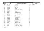
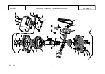
Page 44: ... 18 22 REV 01 2013 3 MOTOR REDUCTION GEAR GROUP TAV 6 0 ED 04 13 ...
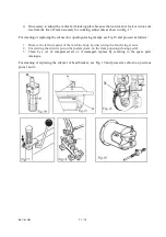
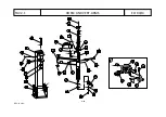
Page 47: ... 21 22 REV 01 2013 AIR LUBRICATOR GROUP TAV 8 1 ED 04 13 ...


