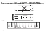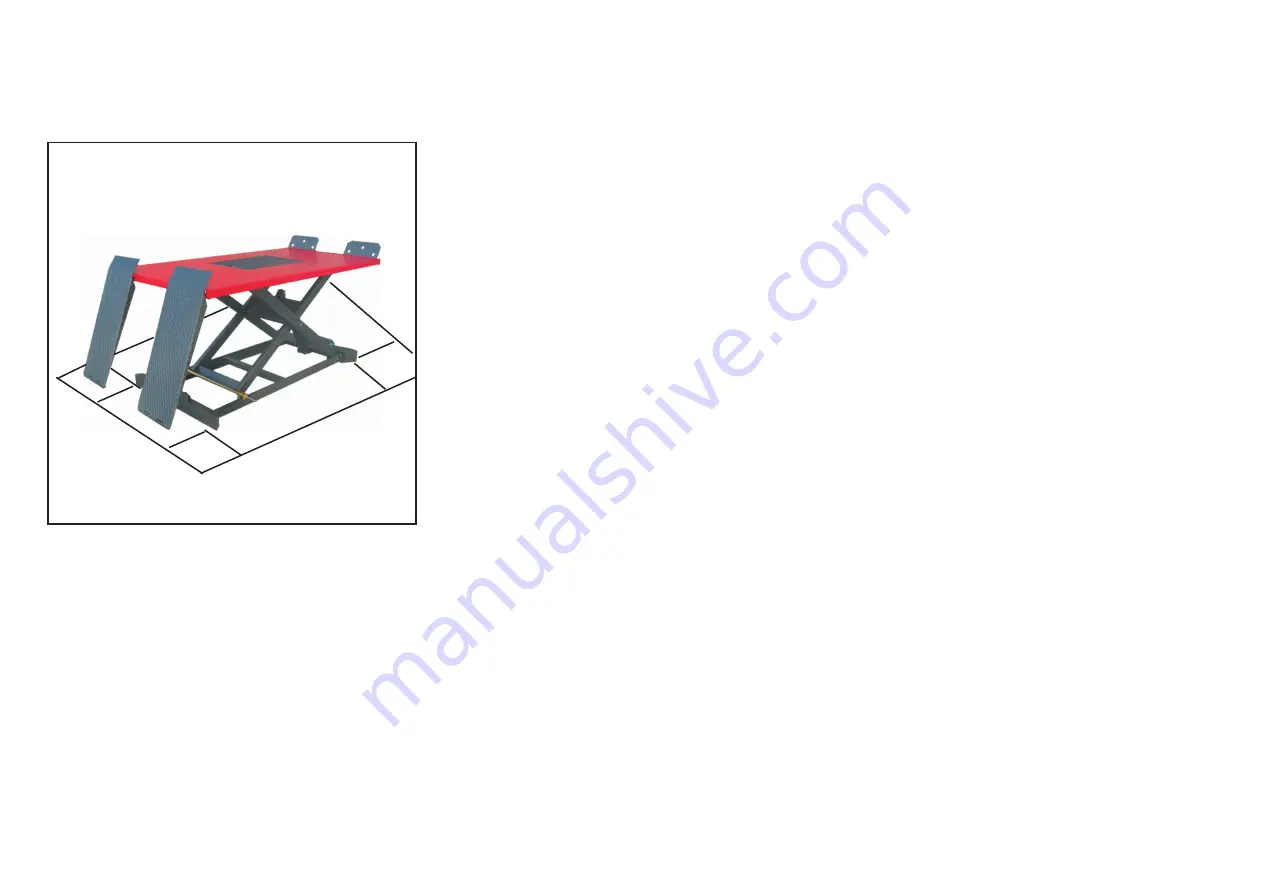
Fig.22 Abb.22
CAP.4
INSTALLAZIONE
QUESTE OPERAZIONI SONO DI COMPETENZA ESCLUSIVA DEI
TECNICI SPECIALIZZATI INCARICATI DAL COSTRUTTORE O DAI
RIVENDITORI AUTORIZZATI.
SE EFFETTUATI DA ALTRE PERSONE POSSONO CREARE SITUA-
ZIONI DI PERICOLO E CAUSARE GRAVI DANNI ALLE PERSONE
E/O AL SOLLEVATORE.
VERIFICA DEI REQUISITI PER L’INSTALLAZIONE
Il sollevatore è costruito per l’impiego in locali chiusi e riparati. Il luogo
prescelto non deve essere vicino a lavaggi, a posti di verniciatura, a de-
positi di solventi o vernici, a locali con lavorazioni che possono creare
atmosfere esplosive.
VERIFICA DI IDONEITA’ DELLE DIMENSIONI DEL LOCALE E
DELLE DISTANZE DI SICUREZZA.
Il sollevatore deve essere installato rispettando le distanze di sicurezza
da muri,colonne, altre macchine, etc... come indicate in fig.22 e secon-
do le eventuali prescrizioni della legislazione vigente nel luogo di instal-
lazione.
Verificare in particolare:
·
altezza: considerare l’altezza dei motocicli da sollevare tenendo con-
to che l’altezza max. del piano di sollevamento è di 1030 mm.
·
distanza dai muri: minimo 500 mm.
·
spazi per lavorare: minimo 500 mm., oltre le dimensioni del veicolo
da sollevare.
·
spazi per la POSTAZIONE DI COMANDO,
·
spazi per la manutenzione, per accessi e vie di fuga in caso di emer-
genze.
·
posizione relativa alle altre macchine,
·
possibilità di realizzare l’allacciamento elettrico.
ILLUMINAZIONE
Tutte le zone della macchina devono essere illuminate in modo unifor-
me e sufficiente per garantire le operazioni di regolazione e manuten-
zione previste nel manuale, evitando zone d’ombra riflessi, abbaglia-
mento e affaticamento della vista.
L’illuminazione deve essere realizzata in accordo con la normativa vi-
gente nel luogo di installazione (a cura dell’installatore dell’impianto di
illuminazione).
PAVIMENTO
Il sollevatore deve essere installato su platea orizzontale di spessore
minimo 150 mm. realizzata in calcestruzzo dosato con resistenza > 30
N/mm2 .
Il pavimento deve inoltre essere piano e ben livellato (10 mm. di tolle-
ranza sul livellamento).
Nel caso di applicazioni particolari, interpellare il costruttore.
CHAP. 4
INSTALLATION
THESE OPERATIONS ARE THE EXCLUSIVE COMPETENCE OF
THE SPECIALIZED ENGINEERS APPOINTED BY THE
MANUFACTURER OR BY THE AUTHORIZED DEALERS.
IF CARRIED OUT BY OTHER PERSONS THEY MAY CREATE
HAZARDOUS SITUATIONS AND CAUSE SERIOUS DAMAGE TO
PERSONS AND/OR THE LIFT.
CHECKING INSTALLATION REQUIREMENTS
The lift is made to be used in closed and sheltered rooms. The chosen
place must not be close to washing or painting stations, stores of thin-
ners or paints, rooms with processing that may create an explosive at-
mosphere.
CHECKING THE SUITABILITY OF THE SIZE OF THE ROOM AND OF
THE SAFETY DISTANCES
The lift must be installed respecting the safety distance from walls, co-
lumns, other machines, etc., as shown in Fig. 22 and according to any
regulations of the legislation in force in the place of installation.
Check in particular:
·
height: consider the height of the motorcycles to be lifted, taking into
account that the max. height of the lifting platform is 1030 mm.;
·
distance from walls: minimum 500 mm.;
·
work spaces: minimum 500 mm., over the dimensions of the vehicle
to be lifted;
·
spaces for the CONTROL STATION;
·
spaces for maintenance, access and escape routes in the event of an
emergency;
·
relative position to other machines;
·
possibility to make the electrical connection.
LIGHTING
All the areas of the machine must be lighted uniformly and sufficiently to
ensure the adjustment and maintenance operations foreseen in this
manual, avoiding areas of shadow, reflection, glare and fatigue to the
eyes.
The lighting must be made in accordance with the current regulations at
the place of installation (to the care of the lighting system installer).
FLOOR
The lift must be installed on a horizontal surface with a minimum thic-
kness of 150 mm. made in concrete with a strength > 30 N/mm2.
In addition, the floor must be flat and well levelled (10 mm. of tolerance
on the levelling).
In the case of special applications, call the manufacturer.
23
10
00
50
0
500
500
Summary of Contents for WML1000Q
Page 2: ......


