background image


OPERATING MANUAL


Pneumatic rotary drive units type ST | DT 


Wesa-Armaturen GmbH 


Phone 

+49 (0)7181-404-0 


Mailto 

info@wesa-armaturen.de 


Page

 10

Spanninger Str. 5 


Fax 

+49 (0)7181-404-33 


Http 

www.wesa-armaturen.de 

Operating manual

D-73650 Winterbach 


Drive units ST | DT 


         Date of issue 10-2019 
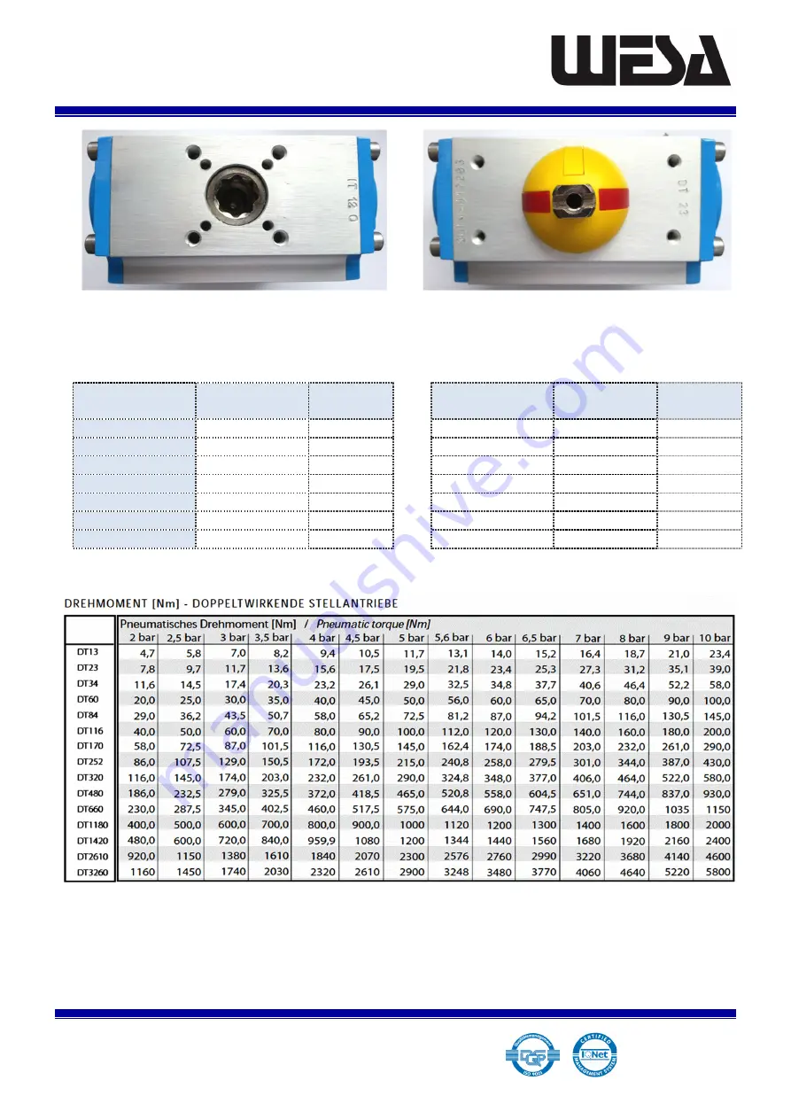


Figure 1:


Figure 2:


View from below of a servo drive unit


with ISO standard installation boreholes 

View from above of a servo drive unit


with ISO standard installation boreholes 


Drive unit Part 
No. 

ISO dimension 

Ø [mm] 


Drive unit Part 
No. 

ISO 

dimension 

Ø [mm] 

DT23 

F03 | F05 

36 | 50 


DT320 

F07 | F10 

70 | 102 

DT34 

F05 | F07 

50 | 70 


DT480 

F10 | F12 

102 | 125 

DT60 

F05 | F07 

50 | 70 


DT660 

F10 | F12 

102 | 125 

DT84 

F05 | F07 

50 | 70 


DT1180 

F14 

140 

DT116 

F05 | F07 

50 | 70 


DT1420 

F14 

140 

DT 170 

F07 | F10 

70 | 102 


DT2610 

F16 

165 

DT252 

F07 | F10 

70 | 102 


DT3260 

F16 

165 


Summary of Contents for DT 170

Page 1: ...ouble action DT PNEUMATIC ROTARY DRIVE UNITS This operating manual contains important information relating to the installation function maintenance and storage of AEROMATIC rotary drive units Please r...

Page 2: ...umatic rotary drive units with rack and pinion gearing 1 0 Introduction 6 0 Installation of components 11 0ISO connections 2 0 Storage 7 0 Double action servo drive units 12 0Torques 3 0 Function char...

Page 3: ...ned to their initial positions The drive pinion returns to its original position through a 90 swing movement Single action servo drive units with reset springs If compressed air is supplied to compres...

Page 4: ...g during the function test Actuate the servo drive unit and the fitting several times by supplying compressed air to the compressed air connections alternately Pay close attention to ensuring that the...

Page 5: ...a rubber or plastic mallet if necessary to tap gently on the upper end of the pinion Then remove the pinion from the bottom whole of the drive housing Fig 5 Tables 2A and 2B show the spare part serie...

Page 6: ...Tighten the screws crossways to ensure that the O rings are correctly positioned 6 11 The screws on the heads must be tightened alternately using the torque specified by the manufacturer See Table 3...

Page 7: ...e units type ST DT Wesa Armaturen GmbH Phone 49 0 7181 404 0 Mailto info wesa armaturen de Page 6 Spanninger Str 5 Fax 49 0 7181 404 33 Http www wesa armaturen de Operating manual D 73650 Winterbach D...

Page 8: ...igure 7 This figure shows the left piston and its front view with details of the numbered seats for the spring inserts Figure 8 This figure shows the right piston and its front view with details of th...

Page 9: ...ring 6 2 2 Piston guide ring 2 Guide 7 2 2 Piston guide slide 2 Guide 8 2 2 Head O ring seal 2 O ring 9 1 Inner regulator rod 10 1 Piston stop O ring seal 11 1 Piston stop guide bushing 12 1 Stop ring...

Page 10: ...e units type ST DT Wesa Armaturen GmbH Phone 49 0 7181 404 0 Mailto info wesa armaturen de Page 9 Spanninger Str 5 Fax 49 0 7181 404 33 Http www wesa armaturen de Operating manual D 73650 Winterbach D...

Page 11: ...View from below of a servo drive unit with ISO standard installation boreholes View from above of a servo drive unit with ISO standard installation boreholes Drive unit Part No ISO dimension mm Drive...

Reviews: