background image

W71E

-

W101E

D - 22391 Hamburg 

 Tel.: + 49 40 60009468-0 

 Fax: + 49 40 536 75 01  

  •

 Equipment Imp.-Exp. GmbH 

 Zitterpappelweg 9

E - M a i l :   i n f o @ w e s c o - n a v y . c o m  

  w w w . w e s c o - n a v y . c o m

Manual / Handbuch

Spare parts list / Ersatzteilliste

Summary of Contents for W121E

Page 1: ...1E W101E D 22391 Hamburg Tel 49 40 60009468 0 Fax 49 40 536 75 01 Equipment Imp Exp GmbH Zitterpappelweg 9 E Mail info wesco navy com www wesco navy com Manual Handbuch Spare parts list Ersatzteillist...

Page 2: ......

Page 3: ......

Page 4: ......

Page 5: ......

Page 6: ......

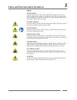
Page 7: ...s MOVING PARTS HAZARD This symbol alerts you to the presence of possible dangerous moving parts within the machine Guards should always be in place when the machine is in operation Be very careful whe...

Page 8: ...ed over to the applicable collection point for the recycling of electrical and electronic equipment Ensuring this product is disposed of correctly you will help prevent potential negative consequences...

Page 9: ...ety Decals Safety decals appear at crucial locations on the machine Failure to maintain legible safety decals could result in injury to the operator or service technician To provide personal safety an...

Page 10: ...t if not avoided will cause severe personal injury or death Do not install or store the washer where it will be exposed to water and or weather 9 Do not tamper with the controls 10 Do not repair or re...

Page 11: ...safety devices 26 Failure to install maintain and or operate this washer according to the manufacturer s instructions 27 may result in conditions which can produce bodily injury and or property damag...

Page 12: ...nd attempt to start the machine The machine should not start with the door unlocked c Close and lock the door and start a cycle Attempt to open the door while the cycle is in progress The door should...

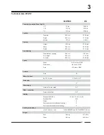
Page 13: ...ch To center 606 mm 23 85 inch Speed Wash 10 50 tr min RPM Distribution 85 tr min RPM Spin 475 tr min RPM G factor Spin 82 Motor 3 phase 4p 1470 tr min 0 75kW 1HP Drain valve 2 Water supply Hard soft...

Page 14: ...91 640 25 2 70 2 76 70 2 76 220 8 66 33 1 3 84 3 31 260 10 24 28 1 1 410 16 14 82 3 23 816 32 12 760 29 92 3 Dimensions W121E A Ventilation soap dispenser B Liquid soap connections C Hard water connec...

Page 15: ...To center 606 mm 23 85 inch Speed Wash 10 50 tr min RPM Distribution 85 tr min RPM Spin 475 tr min RPM G factor Spin 82 Motor 3 phase 4p 1470 tr min 0 75kW 1HP Drain valve 2 Water supply Hard soft war...

Page 16: ...209 8 23 84 3 31 L K 109 4 29 F E D G I C 780 30 71 1204 47 4 1175 46 26 455 17 91 640 25 2 70 2 76 70 2 76 3 Dimensions W151E A Ventilation soap dispenser B Liquid soap connections C Hard water conn...

Page 17: ...18 inch between each machine Surface Anchoring on a metal base The machine must be anchored directly on a concrete base See Label 3 A Bolt M16 5 8 B Concrete base 35 cm C Washer 40x17x4 1 57x0 60x0 15...

Page 18: ...780 30 71 640 25 2 70 2 76 731 28 78 410 16 14 70 2 76 33 1 3 28 1 1 260 10 24 2 2 0 8 7 670 26 38 4 Mounting Bolt Hole Locations for machine W121E Legend metric mm inches...

Page 19: ...770 30 31 2 2 0 8 7 260 10 24 28 1 1 33 1 3 70 2 76 510 20 08 831 32 72 70 2 76 640 25 2 780 30 71 4 Mounting Bolt Hole Locations for machine W151E Legend metric mm inches...

Page 20: ...ents Boiler METRIC US For the W121 E 100L 3 53 ft For the W151 121L 4 23 ft Water connection The diameter of the main drain should be adapted to the water flow and the number of machines It should be...

Page 21: ...C drive provides overload protection for the drive motor However a separate single or three phase circuit breaker must be installed for complete electrical overload protection This prevents damage to...

Page 22: ...y and proper operation the washer extractor must be grounded in accordance with state and local standards If such standards are not available grounding must conform to the National Electric Code artic...

Page 23: ...n switch cover plate at back of machine see chapter dimensions part F Run power cable through the cabinet knock out located directly below the cover plate Before installing obtain and install a cord g...

Page 24: ...ified as the neutral wire to the bottom terminal of the auxiliary contactor on the power contactor switch marked N 200 240 volts 1 Phase 2 wire PE 60 Hertz called 1 phase 60 Hz X voltage With supply p...

Page 25: ...440 480 50 60 3 3 PE 4 10 10 14 2 5 6x2 kW 21 30 30 10 6 0 P 380 415 50 60 3 3 N PE 12 15 16 14 2 5 30 40 40 8 10 0 Q 200 240 50 60 3 3 PE 12 15 16 14 2 5 42 50 50 8 10 0 X 200 240 50 60 1 3 2 3 PE 1...

Page 26: ...X 200 240 50 60 1 3 2 3 PE 12 15 16 14 2 5 N A N A N A N A Alternative Electric Heat Options N 440 480 50 60 3 3 PE 3x3 kW 3x2 kW 26 30 30 10 6 0 P 380 415 50 60 3 3 N PE 34 40 40 8 10 0 Q 200 240 50...

Page 27: ...Check at regular intervals for chemical leaks CAUTION Drill out plugs and nipples before making supply hose connection Failure to do so can cause buildup of pressure and risk a tubing rupture Electric...

Page 28: ...e transformed to other values to drive other type soap pumps Example pumps 24V See Label 7 Also pumps with different operating tension can be combined Example 5 pumps 220V and 1 pump 24V See Label 8 W...

Page 29: ...be connected The right connectors form a potential free output contact as a result of which the operating panel detects when the machine is activated or not The left connectors receive the signal by...

Page 30: ...ar Maximum pressure psi For the W121E WF65 IWF065 IWF014 CWF065 CWF01 3 8 1 2 0 5 5 30 80 5 5 80 For the W151E WF75 IWF074 IWF018 CWF074 3 8 1 2 0 5 5 30 80 5 5 80 For the WF135 WF135 IWF135 IWF030 CW...

Page 31: ...X 200 240 50 60 1 3 2 3 PE 12 15 16 14 2 5 N A N A N A N A Alternative Electric Heat Options N 440 480 50 60 3 3 PE 3x3 kW 3x2 kW 26 30 30 10 6 0 P 380 415 50 60 3 3 N PE 34 40 40 8 10 0 Q 200 240 50...

Page 32: ...ese have been installed It is recommended to leave the door and soap dispenser open after use to ventilate the machine Check for proper door lock operation on a daily basis General maintenance The V b...

Page 33: ...8 Contact Information Nameplate Nameplate Location The nameplate is located at the rear of the machine Always provide the machine s serial number and model number when ordering parts or when seeking t...

Page 34: ...and deficiencies which you cannot resolve yourself contact your distributor Repair and after sales service Machine Type Program Date of installation Installed by Serial number Operation voltage and fr...

Page 35: ...electronic timer micro 20 Manual Operating instructions...

Page 36: ...al 5 Explanation of Safety Messages 6 Important Safety Instructions 7 Operator Safety 9 Operating instructions 12 Machine with start button 12 Machine with coin or token operation 20 Standard programs...

Page 37: ...ds MOVING PARTS HAZARD This symbol alerts you to the presence of possible dangerous moving parts within the machine Guards should always be in place when the machine is in operation Be very careful wh...

Page 38: ...ded over to the applicable collection point for the recycling of electrical and electronic equipment Ensuring this product is disposed of correctly you will help prevent potential negative consequence...

Page 39: ...ARNING Indicates a hazardous situation that if not avoided could cause severe personal injury or death CAUTION Indicates a hazardous situation that if not avoided may cause minor or moderate personal...

Page 40: ...hat if not avoided will cause severe personal injury or death Do not install or store the washer where it will be exposed to water and or weather 9 Do not tamper with the controls 10 Do not repair or...

Page 41: ...safety devices 26 Failure to install maintain and or operate this washer according to the manufacturer s instructions 27 may result in conditions which can produce bodily injury and or property damage...

Page 42: ...start with the door open b Close and lock the door and start a cycle Attempt to open the door while the cycle is in progress The door should not open If the door lock and interlock are not functioning...

Page 43: ...1 10...

Page 44: ...11...

Page 45: ...o 100 programs 0 99 The program number is displayed on the right display By pressing the SELECT button P the next program will be displayed By pressing the ECO button E the previous program will be di...

Page 46: ...as been cut from the machine for more than 24 hours The right display will continue to show the selected program number If a Level stop was programmed which halts the programmer during the filling of...

Page 47: ...the spin LEDs during gentle final spin Led drain distribution low spin high spin coast tumble Interm spin blinking rapidly slowly slowly off Final spin continuously continuously continuously rapidly...

Page 48: ...ammed by means of the ECO button E By pressing it once the stop time is programmed for 10 minutes From now onwards F1 and 10 appear alternately on the middle display By pressing the ECO button E once...

Page 49: ...replaced by a regular wash action During final spin only the programmed low spin time will be completed as regular wash action High spin is skipped in its entirety This function influences the cycle t...

Page 50: ...ety level the door will remain sealed and the display will show SLE Safety Level on the left display Afterwards the display will temporarily show End on the same display and the Start LED will be swit...

Page 51: ...run of the program the time will be stopped The wash bath will be filled to the appropriate level and temperature and the programmed wash action is executed The left display will alternately show temp...

Page 52: ...he program in operation during a longer time span and the second program to be executed during the shorter time span After the first program has been run only the second program number will be display...

Page 53: ...into the machine the display will be switched off and the machine will start During the first 2 minutes after starting the program number is blinking and you can change the program in case of a possib...

Page 54: ...segment is executed This way the program sequence can accurately be followed When a LED blinks the machine is taking up water When a LED blinks slowly the machine is heating up the water Spin LEDs Whe...

Page 55: ...ton Attention If F5 is activated during final spin this segment of the program will be skipped as described above It is however followed by a coast and tumble time to disentangle the linen This specia...

Page 56: ...the ring B suspended on the left side while opening the door Important Central panel control Option Here payment is done through the central panel and not directly into the machine As soon as the paym...

Page 57: ...s The central display will show the letter c Release the button or switch When the letter o appears on the display press the button or pull the switch lever back down again for 5 seconds Now the displ...

Page 58: ...it has been programmed in the technical menu COIN COUNT C Number of coin insertions COIN 2 up to 60 000 This parameter is only indicated if it has been programmed in the technical menu COIN COUNT D In...

Page 59: ...arching is mostly used in very special applications and is therefore not displayed on the front panel Standard programs 0 Starching 1 RINSE COLD COLD 1 HOT WASH 2 BATHS 40 90 C 104 194 F 2 HOT WASH 1...

Page 60: ...rice adjustment for this program A coin value 0 or bigger than 1000 was programmed Example wrong price adjustment for program 5 E4 water level The appropriate water level was not reached after 15 minu...

Page 61: ...peed meter is probably out of order or disconnected Lev The water level was not reached Important When a malfunction occurs during a program the central display will communicate the appropriate error...

Page 62: ...Programmed temperature was not reached Check auxcillary heating system after 80 minutes temperature sensor water safety level switch E6 door lock The door lock was released during the wash cycle Check...

Page 63: ...HVV WKH 6HOHFW EXWWRQ IRU VHFRQGV HHS 3 GHSUHVVHG IRU DQRWKHU VHF IWHU VHFRQGV DSSHDUV E IWHU VHFRQGV WHVW ZLOO DSSHDU IRU VHFRQGV 3XVK WLPHV RQ WKH 2 EXWWRQ ZLWKLQ VHFRQGV 7KH 0LFUR WHVW SURJUDP 2XU...

Page 64: ...VHG H FDQ WHVW WKH GRRU ORFNLQJ PHFKDQLVP E SXVKLQJ WKH 6WDUW 6WRS EXWWRQ KHQ WKH GRRU LV ORFNHG ZH FDQ JR RQ E SUHVVLQJ WKH VHOHFW EXWWRQ 7KH ZKROH GLVSOD DQG DOO V ZLOO OLJKW XS P S P H FRQWLQXH WKH...

Page 65: ...GLVSOD VKRZV HIW DQG WKH GUXP PXVW URWDWH OHIW DW ZDVK VSHHG USP 7KH GLVSOD VKRZV DQG WKH GUXP VWRSV 7KH GLVSOD VKRZV 5LJKW DQG WKH GUXP PXVW URWDWH ULJKW DW ZDVK VSHHG 2U WHVWLQJ IRU PLQXWH 2U WHVWLQ...

Page 66: ...XVW URWDWH ULJKW DW GLVWULEXWLRQ VSHHG USP 7KH GLVSOD VKRZV R DQG WKH GUXP PXVW URWDWH ULJKW DW ORZ VSLQ USP 7KH GLVSOD VKRZV LJK DQG WKH GUXP PXVW URWDWH ULJKW DW KLJK VSLQ USP 2U WHVWLQJ IRU PLQXWH...

Page 67: ...PDFKLQH ZLOO VORZ GRZQ WR ZDVK VSHHG 7KH F FOH FRQWDFW ZLOO FORVH QRZ 7KH DFWXDO WHPSHUDWXUH RI WKH EDWK LV GLVSOD HG LQ RU QOHW YDOYH ZLOO QRZ EH DFWLYDWHG DQG VHFRQGV ODWHU 7KH OHIW GLVSOD VKRZV WKH...

Page 68: ...VKRZV WKH ZDWHU OHYHO QRZ 7KH GUDLQ LV FORVHG DQG ZDVK ULJKW LV DFWLYDWHG QRZ OO LQOHW YDOYHV DUH GHDFWLYDWHG DQG WKH GLVSOD VKRZV QRZ RQO WKH ZDWHU OHYHO 7KH GUDLQ LV VWLOO FORVHG H FDQ FDOLEUDWH WK...

Page 69: ...7 E E E OO VRDS LQOHWV 6 6 ZLOO EH DFWLYDWHG IRU VHFRQGV RQH DIWHU RQH VWDUWLQJ ZLWK 62 3 XULQJ WKH VRDS SXPS WHVW LV DFWLYDWHG 2U ZDLWLQJ IRU VHFRQGV 2U ZDLWLQJ IRU VHFRQGV...

Page 70: ...8 E E E 2U ZDLWLQJ IRU VHFRQGV 2U ZDLWLQJ IRU VHFRQGV 2U ZDLWLQJ IRU VHFRQGV...

Page 71: ...SOD VKRZV DQG DOO ZDWHU LQOHWV ZLOO EH DFWLYDWHG XQWLO WKH VDIHW OHYHO LV UHDFKHG LQ RUGHU WR WHVW WKH KHDWLQJ UHOD V KHQ WKH VDIHW OHYHO LV UHDFKHG WKH GLVSOD ZLOO VKRZ 7 7KH GLVSOD VKRZV DQG WKH KHD...

Page 72: ...HQHG DQG GLVSOD VKRZV 9 DV ORQJ DV WKHUH LV VWLOO ZDWHU LQ WKH WXE KHQ DOO WKH ZDWHU KDV EHHQ GUDLQHG WKH GLVSOD ZLOO VKRZ 225 DQG WKH GRRU ZLOO EH XQORFNHG 7KH GLVSOD VKRZV 1 DQG ZH FDQ WHVW WKH IROO...

Page 73: ...f balance switch NC Mainwash LED Rinse 1 LED Coin 1 NO Rinse 2 LED Coin 2 NO Rinse 3 LED Speed sensor Last rinse LED Thermo overload NO Spin action LED s 7KH WHVW SURJUDP LV GRQH DQG WKH GLVSOD VKRZV...

Page 74: ...lease give full description and state both position and code numbers Thank you Bei Bestellung von Ersazteilen bitte deutlich die Positions und Kodenummer angeben Danke Pour vos commandes de pi ces d t...

Page 75: ...l boven epoxy Cygnus Standard of Commercial OPL PBF 17 Voorpaneel boven epoxy Cygnus Standard of Commercial betaal machines 18 Voorpaneel boven epoxy Cygnus Standard of Commercial betaal machines PBF...

Page 76: ...Inhoudstafel Brug elektrische onderdelen 36 Poederbak PBF1 37 Poederbak PB3 38 Poederbak PB6 39 Onderdelen verwarming 40 Pompen vloeibare zeep Kl debiet 41...

Page 77: ...xy Cygnus Standard or Commercial OPL PBF 17 Front panel above epoxy Cygnus Standard or Commercial coin operated machines 18 Front panel above epoxy Cygnus Standard or Commercial coin operated machines...

Page 78: ...Contents Bridge electrical parts 36 Soap box PBF1 37 Soap box PB3 38 Soap box PB6 39 Parts heating 40 Pumps liquid soap 41...

Page 79: ...s Standard ou Commercial OPL PBF 17 Panneau avant au dessus epoxy Cygnus Standard ou Commercial machines p age 18 Panneau avant au dessus epoxy Cygnus Standard ou Commercial machines p age PBF 19 Pann...

Page 80: ...Index Pont pi ces d tach es lectriques 36 Bac lessive PBF1 37 Bac lessive PB3 38 Bac lessive PB6 39 Pi ces d tach es chauffage 40 Pompes savon liquide Kl d bit 41...

Page 81: ...ard oder Commercial OPL PBF 17 Frontblende oben epoxy Cygnus Standard oder Commercial Maschinen mit Zahlsystem 18 Frontblende oben epoxy Cygnus Standard oder Commercial Maschinen mit Zahlsystem PBF 19...

Page 82: ...Inhalt Br cke elektrische Teile 36 Waschmittelbeh lter PBF1 37 Waschmittelbeh lter PB3 38 Waschmittelbeh lter PB6 39 Teil Heizung 40 Pumpen fl ssige Seife Kl Durchflu 41...

Page 83: ...1 W121E W151E...

Page 84: ...13x26x2 Unterlegscheibe verzinkt 13x26x2 1 07 204 00002 00 Moer staal verzinkt M12 DIN 934 Nut zincked M12 DIN 934 Ecrou galvanis M12 DIN 934 Mutter verzinkt M12 DIN 934 1 08 203 00001 00 Sterrondel g...

Page 85: ...2 W121E W151E...

Page 86: ...5 165 2 13 113 00019 01 plaatje lagerhuis 1mm WF135 165 plate bearing housing 1mm WF135 165 plaquette palier 1mm WF135 165 Platte Lagergeh use 1mm WF135 165 2 13 113 00019 02 plaatje lagerhuis 2mm WF1...

Page 87: ...3 W121E W151E...

Page 88: ...xe tambour 20x30 Toleranzring Trommelachse 20x30 3 04 226 00138 00 V riem 1600 PJ10 V belt 1600 PJ10 Courroie 1600 PJ10 Keilriemen 1600 PJ10 3 05 206 00005 00 Persvijs staal verzinkt M10x30 DIN 933 He...

Page 89: ...4 W121E W151E...

Page 90: ...delle galvanis e 6 4x12 5x1 6 Unterlegscheibe verzinkt 6 4x12 5x1 6 4 04 206 00011 00 Persvijs staal verzinkt M6x50 DIN 933 Hexagon bolt zincked M6x50 din 933 Boulon galvanis M6x50 DIN 933 Sechskantsc...

Page 91: ...5 W121E W151E...

Page 92: ...N 985 Ecrou de s ret M8 galvanis DIN 985 Sicherungsmutter M8 verzinkt DIN 985 5 11 204 00115 00 Moer zelfborgend M5 verzinkt DIN 985 Selflocking nut M5 zincked DIN 985 Ecrou de s ret M5 galvanis DIN 9...

Page 93: ...6 W121E W151E...

Page 94: ...ellenband 40 60 6 15 223 00146 00 Afvoerbuis PVC PVC drain piece Pi ce d vacuation PVC Ablaufst ck PVC 6 16 206 00101 00 Moer M6 met ge ntegreerde sterrondel Nut with integrated castle washer M6 Ecrou...

Page 95: ...7 W121E optie option...

Page 96: ...t pipe 325 Plaque de montage pour tube de vidange Montageplatte Ablassrohr 7 15 201 00007 00 Rondel zacht staal verzinkt 6 5x16x2 Washer zincked 6 5x16x2 Rondelle galvanis e 6 5x16x2 Unterlegscheibe v...

Page 97: ...8 W151E optie option...

Page 98: ...iquid Gummi Waschmittelbeh lter PVC Verbindungsst ck f r Fl ssigseife HW W 8 16 223 00071 00 Serflex 70 90 Clamping ring 70 90 Serflex 70 90 Schellenband 70 90 8 17 206 00101 00 Moer M6 met ge ntegree...

Page 99: ...8 W151E optie option...

Page 100: ...33 223 00016 00 Aquastaatbuisje koper Brass part water level switch Pi ce en laiton aquastat Messingrohr Wasserstandsregler 8 34 209 00644 11 Motor reductie 220V 50 60Hz Motor gear 220V 50 60Hz Moteur...

Page 101: ...9 W121E W151E...

Page 102: ...trek vergrendeling slot t2 Spring interlock t2 Ressort verrouillage serrure t2 Zugfeder T rverriegelung t2 9 18 217 00052 04 Vergrendelingshendel slot t2 Lever interlock device lock t2 Levier de verr...

Page 103: ...9 W121E W151E...

Page 104: ...cyl Senkschraube verzinkt M3x16 zylindrisch 9 37 207 00009 00 Metaalschroef verzinkt M3x16 cilindrisch Screw zincked M3x16 cyl DIN84 Vis galvanis e M3x16 cyl Senkschraube verzinkt M3x16 zylindrisch 9...

Page 105: ...10 W121E W151E...

Page 106: ...55 HF165 Door glass seal WE55 HF165 Joint verre hublot WE55 HF165 Dichtung T rglas WE55 HF165 10 10 118 00046 10 Deur rond mat Door round mat Hublot rond mat T r rund matt 10 11 204 00106 00 Moer RVS...

Page 107: ...11 W121E W151E...

Page 108: ...nus Support pour platine de verrouillage pour Cygnus Montageplatte f r T rschlossplatine Cygnus 11 11 209 02010 00 Print CYGNUS deurvergrendeling Printboard door lock CYGNUS Circuit imprim de verrouil...

Page 109: ...12 W121E W151E...

Page 110: ...x 9 x 1 5 Washer skiffy 3 2 x 9 x 1 5 Rondelle skiffy 3 2 x 9 x 1 5 Unterlegscheibe skiffy 3 2 x 9 x 1 5 12 07 204 00116 00 Moer zelfborgend M3 verzinkt DIN 985 Selflocking nut M3 zincked DIN 985 Ecro...

Page 111: ...12 W121E W151E...

Page 112: ...kking datakaart Cygnus Rubber cover data card Cygnus Couverture en caoutchouc pour carte de donn es Cygnus Gummi Abdeckung Datenkarte Cygnus 12 23 209 02022 00 Dataflash card AT45DCB002 2MB Dataflash...

Page 113: ...13 W121E W151E...

Page 114: ...ataflash card display Cable printboard dataflash card display Cable circuit imprim dataflash card display Kabel platine dataflash card display 13 06 211 00128 00 PVC Afstandshouder voor print 4 2x8x5...

Page 115: ...14 W121E W151E...

Page 116: ...shouder voor print 4 2x8x5 MM PVC separator for printboards 4 2x8x5MM PVC d espacement pour plaquettes lectr 4 2x8x5MM PVC Abstandsh lse f r Printplatte 4 2x8x5MM 14 07 223 00123 00 Rondel skiffy 3 2...

Page 117: ...15 W121E W151E...

Page 118: ...00128 00 PVC Afstandshouder voor print 4 2x8x5 MM PVC separator for printboards 4 2x8x5MM PVC d espacement pour plaquettes lectr 4 2x8x5MM PVC Abstandsh lse f r Printplatte 4 2x8x5MM 15 07 223 00123 0...

Page 119: ...16 W121E W151E...

Page 120: ...taflash card display Cable printboard dataflash card display Cable circuit imprim dataflash card display Kabel platine dataflash card display 16 06 211 00128 00 PVC Afstandshouder voor print 4 2x8x5 M...

Page 121: ...17 W121E W151E...

Page 122: ...00221 00 Kabel print dataflash card display Cable printboard dataflash card display Cable circuit imprim dataflash card display Kabel platine dataflash card display 17 06 211 00128 00 PVC Afstandshoud...

Page 123: ...18 W121E W151E...

Page 124: ...S Dataflash card 18 05 210 00221 00 Kabel print dataflash card display Cable printboard dataflash card display Cable circuit imprim dataflash card display Kabel platine dataflash card display 18 06 21...

Page 125: ...19 W121E W151E...

Page 126: ...rd Platine CYGNUS Dataflash card 19 05 210 00221 00 Kabel print dataflash card display Cable printboard dataflash card display Cable circuit imprim dataflash card display Kabel platine dataflash card...

Page 127: ...20 W121E W151E...

Page 128: ...HC WF135 165 Micro 20 Sigma OPL PB3 Frontpanel upper HC WF135 165 Micro 20 Sigma OPL PB3 Panneau frontal au dessus HC WF135 165 Micro 20 Sigma OPL PB3 Frontblende oben HC WF135 165 Micro 20 Sigma OPL...

Page 129: ...21 W121E W151E...

Page 130: ...stklebendes Abdeckplastik f r M20 SIGM PS40F 21 07 111 01825 00 Voorpaneel boven HC WF135 165 Micro 20 Sigma OPL PBF1 Frontpanel upper HC WF135 165 Micro 20 Sigma OPL PBF1 Panneau frontal au dessus HC...

Page 131: ...22 W121E W151E...

Page 132: ...eerd M4 AZ DIN 6798 Castle washer M4 AZ DIN 6798 Rondelle toile M4 AZ DIN 6798 F cherscheibe M4 AZ DIN 6798 22 06 229 00255 00 Zelfklevende isolatie voor print M20 SIGM PS40F Insulating sticker for M2...

Page 133: ...23 W121E W151E...

Page 134: ...Frontblende oben HC WF135 165 Micro 20 Sigma OPL PB3 23 07 225 00404 00 Bedieningsklever Sigma OPL Operating sticker Sigma OPL Autocollant pour commande Sigma OPL Bedienungsaufkleber Sigma OPL 23 07 2...

Page 135: ...24 W121E W151E...

Page 136: ...cro 20 Sigma OPL PBF1 Panneau frontal au dessus HC WF135 165 Micro 20 Sigma OPL PBF1 Frontblende oben HC WF135 165 Micro 20 Sigma OPL PBF1 24 07 225 10311 00 Bedieningsklever SIGMA OPL PBF1 Operating...

Page 137: ...25 W121E W151E...

Page 138: ...01 Voorpaneel boven HC WF135 165 Micro 20 Sigma munt V2 PB3 Frontpanel upper HC WF135 165 Micro 20 Sigma coin PB3 Panneau frontal au dessus HC WF135 165 Micro 20 Sigma monnayeur V2 PB Frontblende oben...

Page 139: ...26 W121E W151E...

Page 140: ...r print M20 SIGM PS40F Insulating sticker for M20 SIGM PS40F Isolation auto collante pour M20 SIGM PS40F Selbstklebendes Abdeckplastik f r M20 SIGM PS40F 26 06 111 01824 00 Voorpaneel boven HC WF135 1...

Page 141: ...27 W121E W151E...

Page 142: ...DIN 934 Mutter verzinkt M3 DIN 934 27 05 152 00112 00 Omhulsel geldbak Outer casing box coin meter Enveloppe caissette monnaie Au engeh use M nzbeh lter 27 05 152 00112 50 Omhulsel geldbak elektronisc...

Page 143: ...28 W121E W151E...

Page 144: ...rture PVC pour platine Abdeckplastik f r Platine 28 14 209 00552 02 Print PS40F 230V Printboard PS40F 230V Circuit imprim PS40F 230V Platine PS40F 230V 28 15 229 00255 00 Zelfklevende isolatie voor pr...

Page 145: ...29 W121E W151E...

Page 146: ...ack Panneau lat ral WE132 HC135 WF135 HF150 skinplate noir Geh useseitenteil WE132 HC135 WF135 HF150 skinplate Schwarz 29 11 111 60036 00 Zijpaneel WE165 HC165 WF165 HF185 skinplate zwart Side panel W...

Page 147: ...30 W121E W151E...

Page 148: ...nt plate sidepanel HW Pi ce de renforcement panneau lat ral HW Verst rkung Geh useseitenteil HW 30 08 206 00114 00 Persvijs staal verzinkt M6x35 DIN 933 Hexagon bolt zincked M6x35 DIN 933 Boulon galva...

Page 149: ...31 W121E W151E...

Page 150: ...M4 DIN 934 31 11 202 00004 00 Rondel zacht staal verzinkt 4x10x1 DIN 125 Washer zincked 4x10x1 DIN 125 Rondelle galvanis e 4x10x1 DIN 125 Unterlegscheibe verzinkt 4x10x1 DIN 125 31 12 203 00006 00 Ste...

Page 151: ...32 W121E W151E...

Page 152: ...4x10x1 DIN 125 Rondelle galvanis e 4x10x1 DIN 125 Unterlegscheibe verzinkt 4x10x1 DIN 125 32 14 204 00114 00 Moer zelfborgend M4 verzinkt DIN 985 Selflocking nut M4 zincked DIN 985 Ecrou de s ret M4 g...

Page 153: ...33 W121E W151E...

Page 154: ...5 ref Pagina 33 Position 5 33 12 zie blz 33 positie 5 see page 33 position 5 ref page 33 position 5 ref Pagina 33 Position 5 33 13 zie blz 33 positie 5 see page 33 position 5 ref page 33 position 5 re...

Page 155: ...34 W121E W151E...

Page 156: ...ircuit imprim pour savon liquide 220V Platine f r Fl ssigdosierung mit Sicherung 220V 34 05 209 00540 01 Print aansluiting netwerk 1x RJ11 2xPHOENIX Printboard connection network 1x RJ11 2xPHOENIX Cir...

Page 157: ...35 W121E W151E...

Page 158: ...1 IN 8 UIT 35 09 209 02006 00 Print CYGNUS frequentie omvormer Printboard CYGNUS frequency inverter Circuit imprim CYGNUS variateur de fr quence Platine CYGNUS Frequenzumrichter 35 10 209 02000 00 Ho...

Page 159: ...36 W121E W151E...

Page 160: ...1301 Connection terminal 3 poles 6MM grey 2006 1301 Borne de raccordement 3 pole 6MM gris 2006 1301 Anschlu klemme 3 polig 6MM Grau 2006 1301 36 09 209 00623 00 Aansluitklem 2 polig 10MM grijs 2010 12...

Page 161: ...36 W121E W151E...

Page 162: ...vec rondelle toile integr e M6 X 16 Schraube mit F cherscheibe M6 X 16 36 16 209 00309 02 Thermostaat voeler kabel 2m Thermostat detector wire 2m Thermostat d tecteur 2m Thermostatf hler 2m 36 17 225...

Page 163: ...37 W121E W151E...

Page 164: ...0 Micro 20 Sigma munt PBF1 Frontpanel upper HC WF60 100 Micro 20 Sigma coin PBF1 Panneau frontal au dessus HC WF60 100 Micro 20 Sigma monnayeur PBF1 Frontblende oben HC WF60 100 Micro 20 Sigma M nz PB...

Page 165: ...38 W121E W151E...

Page 166: ...VC Verbindungsst ck f r Fl ssigseife 50x50 38 09 223 00013 00 Serflex 40 60 Clamping ring 40 60 Serflex 40 60 Schellenband 40 60 38 10 223 00010 00 Serflex 12 22 Clamping ring 12 22 Serflex 12 22 Sche...

Page 167: ...38 W121E W151E...

Page 168: ...lter f r Fl ssigseife PB3 PB4 38 26 223 00102 30 Poederbak PB3 binnen buitenbak Soapbox PB3 inner outer soapbox Bac savon PB3 bac ext rieur bac int rieur Seifenbeh lter PB3 Aussen Innenbeh lter 38 27...

Page 169: ...39 W121E W151E...

Page 170: ...zeep 50x50 PVC connection piece liquid soap 50x50 PVC pi ce de raccordement savant liquide 50x50 PVC Verbindungsst ck f r Fl ssigseife 50x50 39 09 223 00013 00 Serflex 40 60 Clamping ring 40 60 Serfle...

Page 171: ...40 W121E W151E...

Page 172: ...ed M8x70 DIN 933 Boulon galvanis M8x70 DIN 933 Sechskantschraube verzinkt M8x70 DIN 933 40 05 203 00003 00 Sterrondel gefosfateerd M8 AZ DIN 6798 Castle washer M8 AZ DIN 6798 Rondelle toile M8 AZ DIN...

Page 173: ...41 W121E W151E...

Page 174: ...Doseerpomp vloeibare zeep klein debiet voeding 6 pompen Liquid soap dosing pump feeding 6 small pumps Pompe savon liquide dosage petit d bit alimentation 6 pompe Pumpe Fl ssigseife mit Kleine Durchflu...

Page 175: ......

Page 176: ......

Page 177: ......

Page 178: ......

Page 179: ......

Reviews: