background image

4

ASSEMBLY

The help of a second person is recommended. Set the treadmill in a cleared area and remove all packing
materials. Do not dispose of the packing materials until assembly is completed.

Assembly requires only the

included allen wrench     and wrench              . 

38

13

13

37

37

38

Hole

Holes

Holes

1

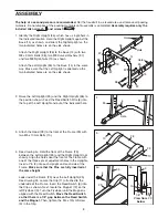
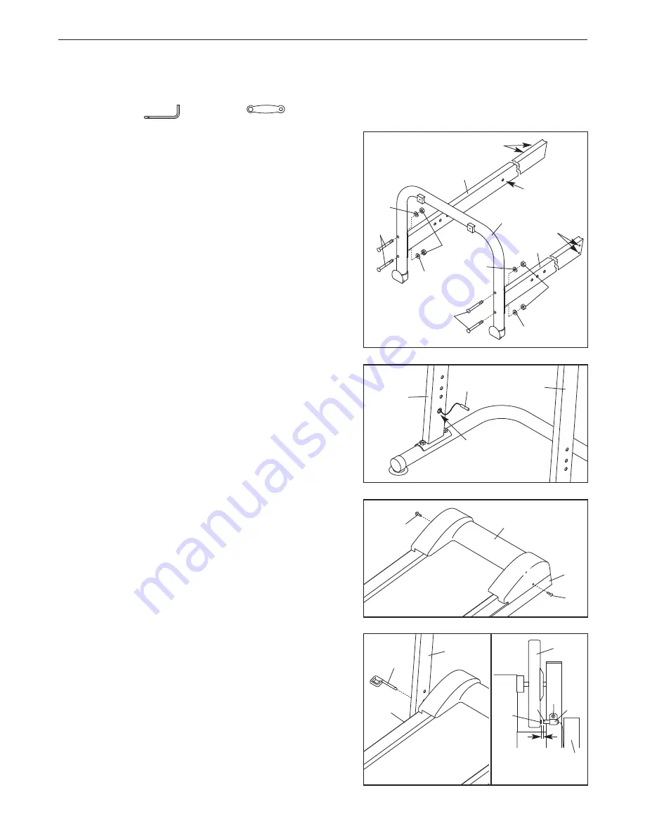
1. Identify the Right Upright (36), which has a single hole in

the indicated location. Hold the Right Upright against the
Base (14) as shown, and orient the Right Upright so the
two indicated holes are on the side shown. 

Attach the Right Upright (36) to the Base (14) with two
M8 x 50mm Bolts (38), two M8 Curved Washers (37),
and two M8 Nylon Nuts (13) as shown.

Attach the Left Upright (35) to the Base (14) in the same
way. Make sure that the Left Upright is oriented so the
two indicated holes are on the side shown.

3. Attach the Hood (28) to the front of the Frame (29) with

two M5 x 10mm Bolts (10).

3

10

10

28

29

2. Raise the Left Upright (35) and the Right Upright (36) to

the position shown. Feed the Reed Switch Wire (6) into
the top of the Left Upright and out of the indicated hole.

2

6

Hole

35

36

36

35

14

37

37

4a

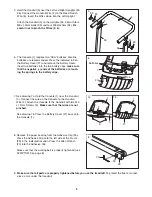
4. See drawing 4a. Hold the front of the Frame (29)

between the Left Upright (35) and the Right Upright (not
shown). Align the holes near the front of the Frame with
one of the three sets of adjustment holes in the Uprights.
Insert a Pin (4) into each Upright and each side of the
Frame. 

Make sure that the Pins are fully inserted at

the same height.

Look under the Frame (29) near the Left Upright (35).
See drawing 4b. Locate the Clip (11) attached to the
underside of the Frame. Insert the Reed Switch (6) into
the Clip as shown. Next, locate the Magnet (12) on the
left Flywheel (9). Turn the Flywheel until the Magnet is
aligned with the Reed Switch. 

Move the Reed Switch

so that there is a 1/8” gap between the Reed Switch
and the Magnet. 
Then, tighten the M4 x 12mm Screw
(3) in the Clip.

4

29

12

9

3

11

6

1/8”

View from

below

35

4b

29

Summary of Contents for 831.291030

Page 1: ...ON Read all precautions and instruc tions in this manual before using this equipment Save this manual for future reference Assembly Operation Maintenance Part List and Drawing TREADMILL EXERCISER User...

Page 2: ...s away from the treadmill at all times 8 The treadmill should not be used by persons weighing over 250 pounds Never allow more than one person on the treadmill at a time 9 Wear appropriate clothing wh...

Page 3: ...ng less than half the space of other treadmills For your benefit read this manual carefully before using the treadmill If you have questions after read ing this manual call 1 800 4 MY HOME 1 800 469 4...

Page 4: ...wo M5 x 10mm Bolts 10 3 10 10 28 29 2 Raise the Left Upright 35 and the Right Upright 36 to the position shown Feed the Reed Switch Wire 6 into the top of the Left Upright and out of the indicated hol...

Page 5: ...itch Wire 6 Insert the Wires down into the Left Upright Attach the Handrail 5 to the Uprights 35 36 with four M8 x 15mm Bolts 33 and four M8 Washers 34 Be careful not to pinch the Wires 2 6 5 Batterie...

Page 6: ...proximate num ber of calories you have burned Scan This mode displays the Speed Distance Time Odometer and Calorie modes Follow the steps below to operate the console 1 Turn on the power To turn on th...

Page 7: ...lift with your legs rather than your back Raise the treadmill to the vertical position 2 Hold the treadmill securely with your left hand as shown Insert a Pin 4 into the hole in the right side of the...

Page 8: ...urn When the tension of the walking belt is correct you should be able to lift each side of the walking belt 2 to 3 inches Walk on the treadmill for a few minutes Repeat until the walking belt is prop...

Page 9: ...for energy If your goal is to burn fat adjust the intensity of your exercise until your heart rate is between the lower two numbers in your training zone as you exercise Aerobic Exercise If your goal...

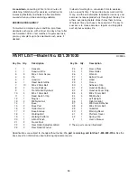
Page 10: ...ption Specifications are subject to change without notice If a part is missing call toll free 1 800 999 3756 See the back cover for information about ordering replacement parts PART LIST Model No 831...

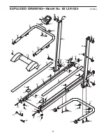
Page 11: ...9 14 4 13 6 8 12 3 9 29 10 7 27 16 20 4 7 7 7 7 10 24 23 15 7 15 7 16 7 21 7 21 8 22 11 17 17 36 35 33 34 32 31 28 10 10 2 40 38 37 38 41 41 26 6 34 33 13 37 13 37 39 7 3 32 31 42 30 EXPLODED DRAWING...

Page 12: ...ser contact the nearest Sears Service Center throughout the United States and Sears will repair or replace the Treadmill Exerciser free of charge This warranty does not apply when the Treadmill Exerci...

Reviews: