10
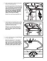
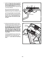
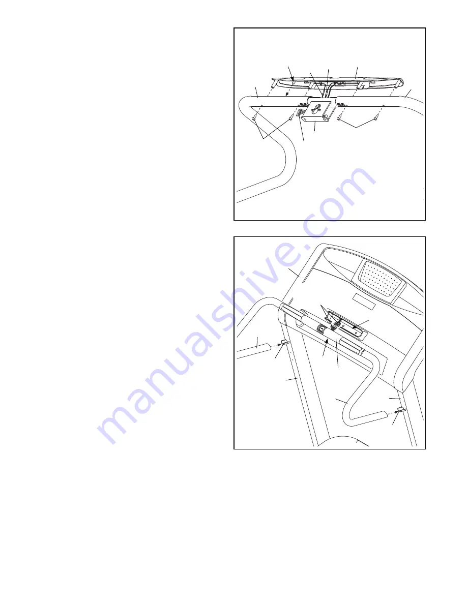
9. Hold the Pulse Assembly (72) near the Handrail
Bracket (70). Orient the Pulse Assembly so
that the indicated plastic post will fit into the
hole in the Right Handrail (71). Connect the
two Pulse Ground Wires (86) to the ground wires
on the Pulse Assembly.
Next, insert the wire harness on the Pulse
Assembly (72) into the top of the Handrail
Bracket (70) and pull it out of the side as shown.
Set the Pulse Assembly (72) on the Handrails
(69, 71). Insert the excess ground wire into the
Handrails. Attach the Pulse Assembly with four
#8 x 3/4” Screws (7). Be careful not to over-
tighten the Screws. Be careful not to pinch
any wires.
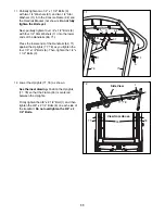
10. Hold the handrail assembly near the console
assembly. Connect the wire harness extending
from the handrail assembly to the wire har-
ness extending from the console assembly. See
the inset drawing in step 6. The connectors
should slide together easily and snap into
place. If they do not, turn one connector and try
again. IF YOU DO NOT CONNECT THE CON-
NECTORS PROPERLY, THE CONSOLE MAY
BECOME DAMAGED WHEN YOU TURN ON
THE POWER.
Set the Handrail Bracket (70) in the slot in the
console assembly as you slide the ends of the
Handrails (69, 71) onto the brackets on the
Uprights (77, 78). Be careful not to pinch any
wires.
7
71
69
86
7
Post
72
9
70
Pulse
Wires
Wire Harness
69
70
77
78
Slot
Bracket
Console
Assembly
Handrail
Assembly
Bracket
10
71
Wire
Harnesses


