background image

ASSEMBLY

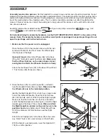
Assembly requires two persons.

Set the treadmill in a cleared area and remove all packing materials. Do not

dispose of the packing materials until assembly is completed. Note: The underside of the treadmill walking belt is
coated with high-performance lubricant. During shipping, a small amount of lubricant may be transferred to the
top of the walking belt or the shipping carton. This is a normal condition and does not affect treadmill perfor-
mance. If there is lubricant on top of the walking belt, simply wipe off the lubricant with a soft cloth and a mild,
non-abrasive cleaner.

Assembly requires the included hex keys    

and your own phillips screwdriver                           , wire

cutters                 , and needlenose pliers                      .

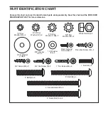
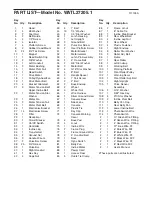
For help identifying the assembly hardware, see the PART IDENTIFICATION CHART in the centre of this
manual. Note: The assembly hardware and other small parts are packaged in separate part bags. Do not
open the part bags until instructed to do so.

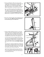
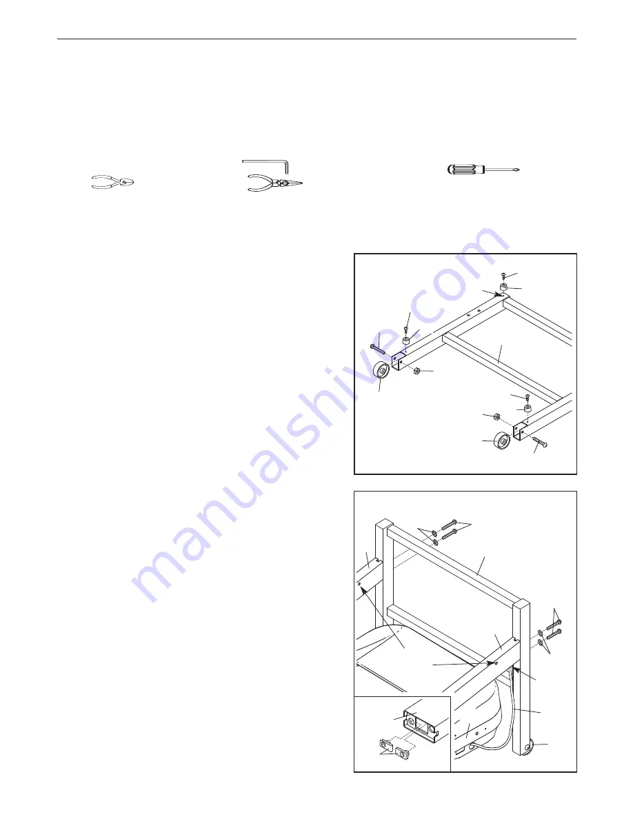
1.

Make sure that the power cord is unplugged.

Place the Base (79) in the position shown, with the indi-
cated small holes on top. Next, place the Wheels (63)
into the ends of the Base.  

Open part bag A. 

Attach the Wheels (63) to the Base

(79) with 2” Bolts (61) and Wheel Nuts (64). 

Make sure

that the Wheel Nuts are on the sides shown; do not
overtighten the Bolts; the Wheels should turn freely.

Attach the four Base Pads (73) to the Base (79) with four
1” Tek Screws (60) (three are shown).

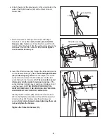
2. Raise the Base (79) to a vertical position, and hold it

near the treadmill Frame (96) as shown. 

Make sure that

the Wheels (63) are in the indicated position.

Identify the Right Upright (104), which has a large round
hole in the indicated location. Feed the Wire Harness
(65) into the hole and out of the top of the Right Upright.
Make sure that there are two U-nuts (74) in the lower
end of the Right Upright (see drawing 2a). Hold the Right
Upright against the Base (79) as shown. 

Make sure that

the Right Upright is oriented so the pivot hole is in the
position shown.

Hand tighten two 3” Bolts (58) with two

5/16” Star Washers (57) into the Base and the Right
Upright. 

Attach the Left Upright (47) to the Base (79) in the same
way. Note: There is not a wire harness on the left side.

With the help of a second person, raise the Uprights (47,
104) to a vertical position.

60

73

Small Hole

61

73

63

64

79

60

63

60

1

Pivot

Holes

79

58

57

47

58

57

65

63

2a

74

104

6

104

2

61

64

73

96

Round

Hole

Summary of Contents for Cadence E-30 Treadmill

Page 1: ...lete sat isfaction through direct assis tance from our factory TO AVOID DELAYS PLEASE CALL DIRECT TO OUR TOLL FREE CUSTOMER HOT LINE The trained technicians on our Customer Hot Line will provide immed...

Page 2: ...TMENT 10 HOW TO FOLD AND MOVE THE TREADMILL 16 TROUBLESHOOTING 17 CONDITIONING GUIDELINES 19 ORDERING REPLACEMENT PARTS Back Cover Note A PART IDENTIFICATION CHART an EXPLODED DRAWING and a PART LIST...

Page 3: ...faces 13 Never move the walking belt while the power is turned off Do not operate the treadmill if the power cord or plug is damaged or if the treadmill is not working properly See TROU BLESHOOTING on...

Page 4: ...stment procedures de scribed in this manual Never remove the motor hood unless instructed to do so by an authorized service representative Servicing other than the procedures in this manual should be...

Page 5: ...s after read ing this manual see the front cover of this manual To help us assist you please note the product model number and serial number before contacting us The model number of the treadmill is W...

Page 6: ...Wheels 63 into the ends of the Base Open part bag A Attach the Wheels 63 to the Base 79 with 2 Bolts 61 and Wheel Nuts 64 Make sure that the Wheel Nuts are on the sides shown do not overtighten the B...

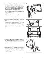
Page 7: ...not shown in the same way Note You may need to tip the Left Handrail to one side as you insert the bracket There is not a wire harness in the left Upright not shown 3 Hold an Upright Spacer 59 agains...

Page 8: ...s 38 Attach the Console Base 67 to the Right Handrail 40 and the Left Handrail not shown with six 3 4 Screws only three Screws are shown Start all six Screws before tightening them do not overtighten...

Page 9: ...the knob from the pin Make sure that the col lar and the spring are on the pin Insert the pin into the Latch Housing 46 and then tighten the knob back onto the pin 46 Pin Spring Knob Collar 11 38 67...

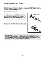
Page 10: ...g Important If the power cord is damaged it must be replaced with a manufacturer recommended power cord See drawing 1 Plug the indicated end of the power cord into the socket on the treadmill See draw...

Page 11: ...gram automatically controls the speed and in cline of the treadmill as it guides you through an effec tive workout To use the manual mode of the console follow the steps beginning on page 12 To use a...

Page 12: ...and begin walking As you exercise change the speed of the walking belt as desired by pressing the Speed increase and decrease buttons Each time a button is pressed the speed setting will change by 0...

Page 13: ...lected the Distance display will show the total number of miles or kilometers that the walking belt has moved and the Time Pace display will show the total number of hours that the tread mill has been...

Page 14: ...n HOW TO USE A PRESET PROGRAM Insert the key into the console See HOW TO TURN ON THE POWER on page 12 Select one of the eight preset programs Press the Program but ton repeatedly until the desired pre...

Page 15: ...t ends The walking belt will then slow to a stop If the speed or incline setting is too high or too low at any time during the program you can manually override the setting by pressing the Speed or In...

Page 16: ...out of direct sunlight Do not leave the treadmill in the storage position in temperatures above 30 C 85 F HOW TO MOVE THE TREADMILL Before moving the treadmill convert the treadmill to the storage pos...

Page 17: ...wait for five minutes and then press the switch back in d Check the on off switch located on the treadmill near the power cord The switch must be in the on position PROBLEM The power turns off during...

Page 18: ...and run the treadmill for a few minutes Repeat until the walking belt is properly tightened c If the walking belt still slows when walked on please see the front cover of this manual PROBLEM The walk...

Page 19: ...that requires large amounts of oxygen for prolonged periods of time This increases the demand on the heart to pump blood to the muscles and on the lungs to oxygenate the blood For aerobic exercise ad...

Page 20: ...ail Bolt 78 2 5 16 Star Washer 57 4 2 Bolt 61 2 Pulse Bar Screw 37 2 4 Frame Bolt 54 2 3 8 Washer 12 2 10 Star Washer 108 2 3 4 Tek Screw 9 2 5 16 Washer 106 2 1 Tek Screw 60 4 Remove this chart and u...

Page 21: ...Motor Bolt 57 4 5 16 Star Washer 58 4 3 Bolt 59 2 Upright Spacer 60 4 1 Tek Screw 61 2 2 Bolt 62 2 Base Endcap 63 2 Wheel 64 4 Wheel Nut 65 1 Wire Harness 66 1 Silver Ground Screw 67 1 Console Base 6...

Page 22: ...32 26 34 27 27 28 27 27 29 30 20 20 27 2 86 86 9 9 9 9 16 59 9 10 11 9 7 9 8 9 8 103 59 9 3 7 9 9 96 4 81 101 100 99 50 5 93 95 97 98 95 41 50 4 5 3 1 9 9 7 7 94 110 21 44 44 21 22 24 25 17 15 19 24...

Page 23: ...es with respect to any economic loss loss of property loss of revenues or profits loss of enjoyment or use costs of removal or installation or other consequential damages of whatsoever nature Some sta...

Reviews: