background image

10

MAINTENANCE 

CONSOLE TROUBLE-SHOOTING

If the console does not function properly, the batteries
should be replaced. To replace the batteries, see
assembly step 6 on page 6. In addition, make sure
that the console wire is connected to the extension
wire. See assembly step 6 on page 6. 

HOW TO ADJUST THE REED SWITCH

If the console does not display correct feedback, the
reed switch should be adjusted. To adjust the reed
switch, the Side Shield (27) must first be removed.
Remove the Crank Cover (62) and the 5/16Ó x 3/4Ó
Tap Screw (18) from the left Crank Arm (10). Slide the
left Crank Arm off the Crank Shaft (11). Remove the
right Crank Arm (not shown) in the same way. 

Remove the three M4 x 16mm Screws (42) from each
side of the Side Shield (27).

Hold the Side Shield (27) near the back and pull it
apart slightly until the Side Shield can be lifted off the
ends of the Crank Shaft (11). Remove the Side Shield.

Do not pull the Side Shield apart at the top or the
seam may be broken.

Next, locate the
Reed Switch (48).
Turn the Pulley
(19) until the
Magnet (55) is
aligned with the
Reed Switch.
Loosen, but do
not remove, the
M4 x 12mm
Screw (51). Slide
the Reed Switch
slightly toward or away from the Magnet. Make sure
that the Magnet will not hit the Reed Switch. Retighten
the Screw. Turn the Pulley (19) for a moment. Repeat
until the console displays correct feedback. When the
Reed Switch is correctly adjusted, reattach the Side
Shield and the Crank Arms. 

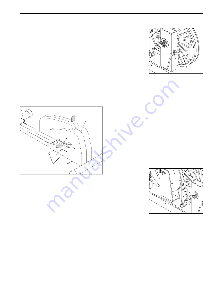
HOW TO ADJUST THE RESISTANCE STRAP

If the pedals do not have enough resistance, even
when the resistance knob is turned to the maximum
setting, the Resistance Strap (31) may need to be
adjusted. To adjust the Resistance Strap, the side
shield must first be removed. Refer to the instructions
at the left to remove the side shield. 

Turn the resistance knob to the lowest setting. (See
HOW TO ADJUST THE RESISTANCE OF THE 
PEDALS on page 5.) Grip the end of the Resistance
Strap (31) and
pull it away from
the rest of the
Strap. Next, pull
the end of the
Strap up to
remove any
slack. Then press
the end of the
Strap against the
rest of the Strap
as shown. Turn
the Pulley (19) for
a moment to make sure that there is not too much
resistance. When the Resistance Strap is properly
adjusted, reattach the Side Shield and the Crank
Arms.

48

19

31

55

51

19

27

10

11

18

62

Back

Top

42

Summary of Contents for Eclipse 2 WLEL45071

Page 1: ...reference Model No WLEL45071 Serial No Serial Number Decal QUESTIONS If you have questions or if there are missing or damaged parts please call direct to our toll free Customer Hot Line The trained te...

Page 2: ...he handlebars when mounting dismounting and using the ECLIPSE II Step onto and off the pedal that is in the lowest position when mounting and dismounting 9 When you stop exercising allow the pedals to...

Page 3: ...ECLIPSE II If you have additional ques tions please call our Customer Service Department toll free at 1 800 999 3756 Monday through Friday 6 a m until 6 p m Mountain Time excluding holidays To help us...

Page 4: ...e dash indicates the quantity needed for assembly Note Some small parts may have been pre attached for shipping If a part is not in the parts bag check to see if it has been pre attached M10 Nylon Loc...

Page 5: ...persons Place all parts of the WESLO ECLIPSE II in a cleared area and remove the packing materials Do not dispose of the packing materials until assembly is completed Assembly requires a phillips scr...

Page 6: ...en the Pedal Bolt into the left Crank Arm 10 Tighten a 1 2 Nylon Locknut 9 onto the Pedal Bolt If the these parts are not tight the product may be damaged Repeat this step to attach the Right Pedal Le...

Page 7: ...nce of the pedals with the resistance knob mounted on the upright To increase the resistance turn the knob clockwise to decrease the resistance turn the knob counterclockwise HOW TO ADJUST THE HANDLEB...

Page 8: ...u The graphs on the left side of the console show how the target pace will change during each program see the drawing above Each graph is divided into ten columns and each column represents a two minu...

Page 9: ...nual mode Begin your workout If you selected the manual mode go to step 4 If you selected one of the pacer programs two columns of bars will appear in the display The left column will show one bar sho...

Page 10: ...with the Reed Switch Loosen but do not remove the M4 x 12mm Screw 51 Slide the Reed Switch slightly toward or away from the Magnet Make sure that the Magnet will not hit the Reed Switch Retighten the...

Page 11: ...that the Flywheel is straight and retighten the M8 Flange Nuts 23 When the Drive Belt is properly adjusted reattach the Side Shield and the Crank Arms HOW TO TIGHTEN THE CRANK If the Crank Arms 10 be...

Page 12: ...e stored fat calories for energy If your goal is to burn fat it may be helpful to use the Fat Burn program to help you to reach your goal See pages 8 and 9 Aerobic Exercise If your goal is to strength...

Page 13: ...ching of the achilles tendons bend your back leg as well Stretches Calves achilles tendons and ankles 4 Quadriceps Stretch With one hand against a wall for balance reach back and grasp one foot with y...

Page 14: ...2 Pedal 30 1 Resistance Strap Bracket 31 1 Resistance Strap 32 1 Drive Belt 33 1 Resistance Cable w Spring 34 1 Resistance Knob 35 2 Handgrip 36 2 Upper Extension Tube Endcap Key No Qty Description 37...

Page 15: ...21 40 30 22 23 24 25 26 33 11 9 10 39 32 47 19 16 12 13 51 48 47 13 15 17 9 12 14 18 10 39 8 3 47 1 58 57 59 57 56 20 61 22 23 24 25 26 39 31 55 6 49 49 65 65 66 54 54 66 54 54 68 68 45 45 63 63 44 44...

Page 16: ...cient proof of purchase All returns must be pre authorized by ICON This warranty does not extend to any product or damage to a product caused by or attributable to freight damage abuse misuse improper...

Reviews: