background image

6

6

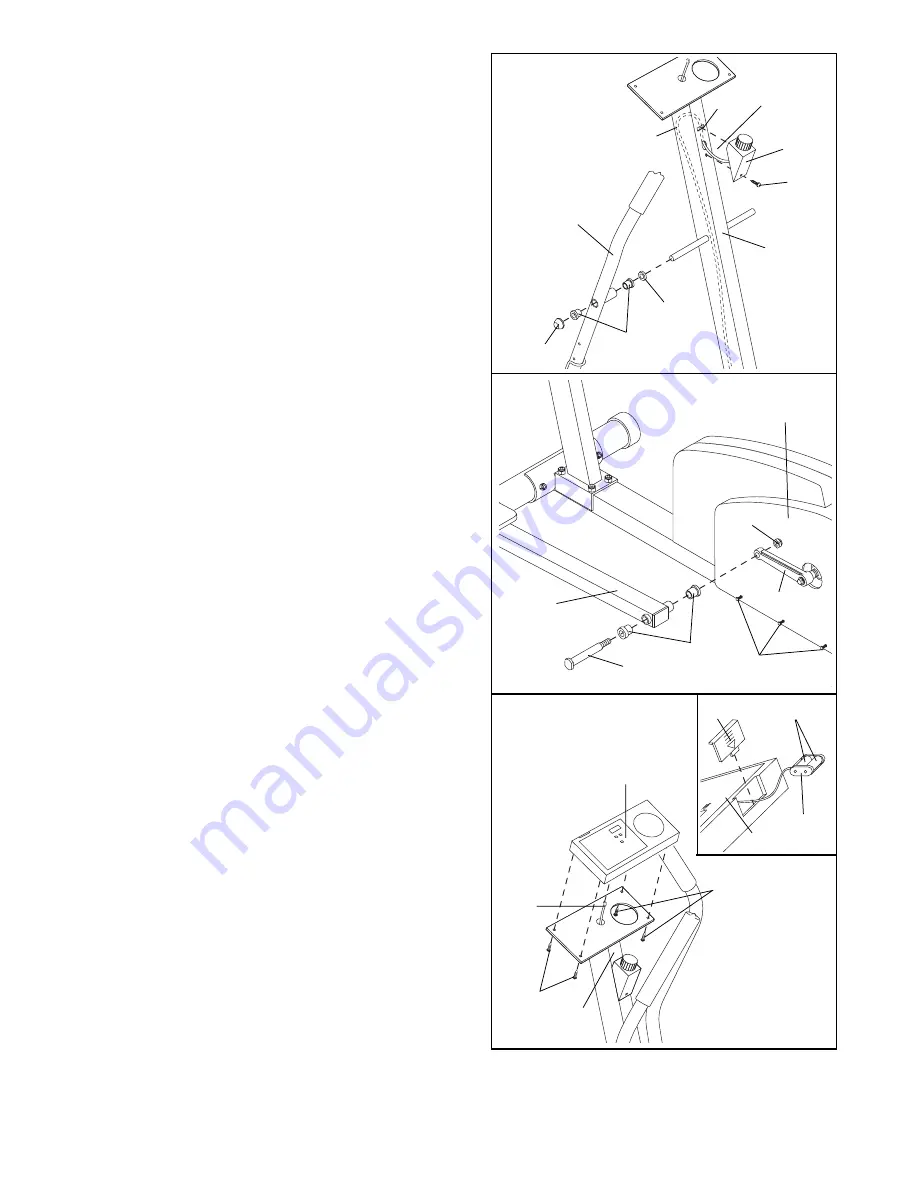
6. Plug the Extension Wire (49) into the socket in the

back of the Console (52). Feed the wire down into the
Upright (2). Attach the Console (52) to the Upright with
four M4 x 18mm Screws (69). 

Be careful to avoid

pinching the wire.

The Console (52) requires two ÒAAÓ batteries (not
included). Alkaline batteries are recommended. 

To install batteries, first slide up the Battery Cover (60)
and carefully remove the battery clip from the Console
(52). Insert two batteries into the battery clip as shown.

Make sure that the negative ends of the batteries
(marked ÒÐÓ) are touching the springs in the 
battery clip. 

Replace the battery clip and close the

Battery Cover.

5. Tighten the three M4 x 16mm Screws (42) on each

side of the Side Shield (27).

Press two Bushings (39) into the Left Pedal Leg (3) as
shown. Insert a Pedal Bolt (8) into the Pedal Leg.
Tighten the Pedal Bolt into the left Crank Arm (10).
Tighten a 1/2Ó Nylon Locknut (9) onto the Pedal Bolt. 

If

the these parts are not tight the product may be
damaged.

Repeat this step to attach the Right Pedal Leg (not
shown).

5

49

69

2

69

52

4. Slide a Handlebar Spacer (46) onto the left axle on the

Upright (2). Make sure that the open side of the
Handlebar Spacer is facing the Upright. Make sure that
there are two Bushings (39) in the Left Handlebar.
Slide the Left Handlebar onto the left axle on the
Upright (2). Tap a 5/8Ó Axle Cap (43) onto the axle.

Repeat this step to attach the Right Handlebar (not
shown).

Feed the Resistance Cable (33) up into the Upright (2)
to form a loop as shown. Insert the tab on the Cable
Cover (53) into the indicated slot in the Upright. Attach
the Cable Cover with an M4 x 16mm Screw (42).

39

42

8

10

3

9

27

4

39

43

46

6

2

33

53

Slot

Loop

42

Batteries

60

Battery
Clip

52

7.

Make sure that all parts of the ECLIPSE II are properly tightened. 

To protect the floor or carpet from 

damage, place a mat under the ECLIPSE II.

Summary of Contents for Eclipse 2 WLEL45071

Page 1: ...reference Model No WLEL45071 Serial No Serial Number Decal QUESTIONS If you have questions or if there are missing or damaged parts please call direct to our toll free Customer Hot Line The trained te...

Page 2: ...he handlebars when mounting dismounting and using the ECLIPSE II Step onto and off the pedal that is in the lowest position when mounting and dismounting 9 When you stop exercising allow the pedals to...

Page 3: ...ECLIPSE II If you have additional ques tions please call our Customer Service Department toll free at 1 800 999 3756 Monday through Friday 6 a m until 6 p m Mountain Time excluding holidays To help us...

Page 4: ...e dash indicates the quantity needed for assembly Note Some small parts may have been pre attached for shipping If a part is not in the parts bag check to see if it has been pre attached M10 Nylon Loc...

Page 5: ...persons Place all parts of the WESLO ECLIPSE II in a cleared area and remove the packing materials Do not dispose of the packing materials until assembly is completed Assembly requires a phillips scr...

Page 6: ...en the Pedal Bolt into the left Crank Arm 10 Tighten a 1 2 Nylon Locknut 9 onto the Pedal Bolt If the these parts are not tight the product may be damaged Repeat this step to attach the Right Pedal Le...

Page 7: ...nce of the pedals with the resistance knob mounted on the upright To increase the resistance turn the knob clockwise to decrease the resistance turn the knob counterclockwise HOW TO ADJUST THE HANDLEB...

Page 8: ...u The graphs on the left side of the console show how the target pace will change during each program see the drawing above Each graph is divided into ten columns and each column represents a two minu...

Page 9: ...nual mode Begin your workout If you selected the manual mode go to step 4 If you selected one of the pacer programs two columns of bars will appear in the display The left column will show one bar sho...

Page 10: ...with the Reed Switch Loosen but do not remove the M4 x 12mm Screw 51 Slide the Reed Switch slightly toward or away from the Magnet Make sure that the Magnet will not hit the Reed Switch Retighten the...

Page 11: ...that the Flywheel is straight and retighten the M8 Flange Nuts 23 When the Drive Belt is properly adjusted reattach the Side Shield and the Crank Arms HOW TO TIGHTEN THE CRANK If the Crank Arms 10 be...

Page 12: ...e stored fat calories for energy If your goal is to burn fat it may be helpful to use the Fat Burn program to help you to reach your goal See pages 8 and 9 Aerobic Exercise If your goal is to strength...

Page 13: ...ching of the achilles tendons bend your back leg as well Stretches Calves achilles tendons and ankles 4 Quadriceps Stretch With one hand against a wall for balance reach back and grasp one foot with y...

Page 14: ...2 Pedal 30 1 Resistance Strap Bracket 31 1 Resistance Strap 32 1 Drive Belt 33 1 Resistance Cable w Spring 34 1 Resistance Knob 35 2 Handgrip 36 2 Upper Extension Tube Endcap Key No Qty Description 37...

Page 15: ...21 40 30 22 23 24 25 26 33 11 9 10 39 32 47 19 16 12 13 51 48 47 13 15 17 9 12 14 18 10 39 8 3 47 1 58 57 59 57 56 20 61 22 23 24 25 26 39 31 55 6 49 49 65 65 66 54 54 66 54 54 68 68 45 45 63 63 44 44...

Page 16: ...cient proof of purchase All returns must be pre authorized by ICON This warranty does not extend to any product or damage to a product caused by or attributable to freight damage abuse misuse improper...

Reviews: