7
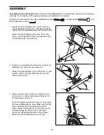
5. Identify the Left Pivot Arm (6), which is marked with a
sticker that has an “L” on it. Make sure that there are
two Pivot Bushings (9) in the Left Pivot Arm. Slide the
Left Pivot Arm onto the Pivot Axle, making sure that it
is oriented as shown. Put a Pivot Washer (54) onto
an M8 x 19mm Button Screw (10) and tighten the
Button Screw into the Pivot Axle.
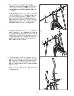
6. Insert a Handlebar (12) into the Right Pivot Arm (7).
Slide the Foam Grip (13) up to expose the mounting
holes. Secure the Handlebar with two M5 x 30mm
Button Bolts (51) and two M5 Nylon Locknuts (52).
Slide the Foam Grip down over the Button Bolts and
Nylon Locknuts.
Attach the other Handlebar to the Left Pivot Arm (6) in
the same manner.
5
9
10
54
9
6
13
51
52
6
7
6
11
12
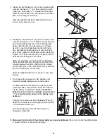
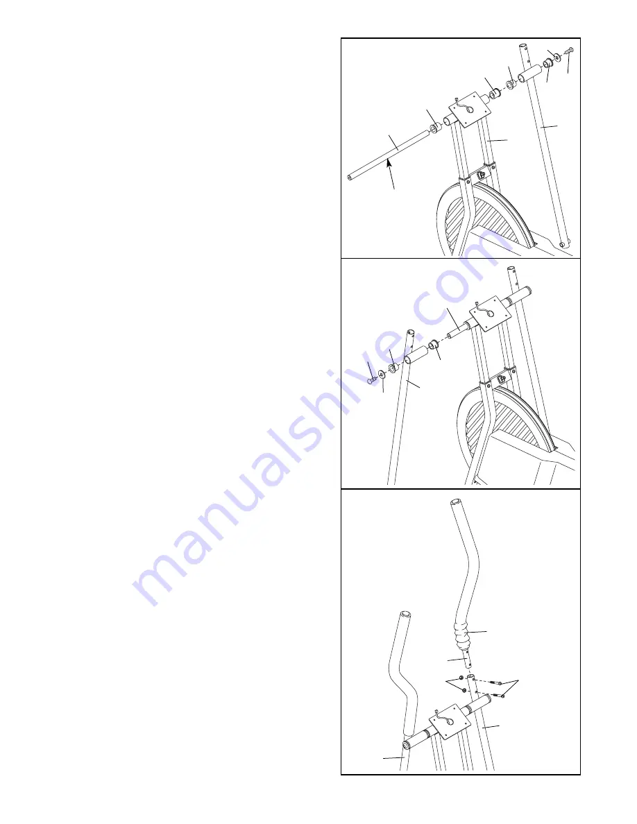
4. Make sure that the two Upright Bushings (8) are
inserted into the Upright (2). Apply a thin film of the
included grease to the length of the Pivot Axle (11).
Insert the Pivot Axle into the Upright Bushings and
the Upright.
Identify the Right Pivot Arm (7), which is marked with
a sticker that has an “R” on it. Make sure that there
are two Pivot Bushings (9) in the Right Pivot Arm.
Slide the Right Pivot Arm onto the Pivot Axle (11),
making sure that it is oriented as shown. Put a Pivot
Washer (54) onto an M8 x 19mm Button Screw (10)
and tighten the Button Screw into the Pivot Axle.
4
9
8
8
2
7
11
Grease
10
9
54


