background image

5

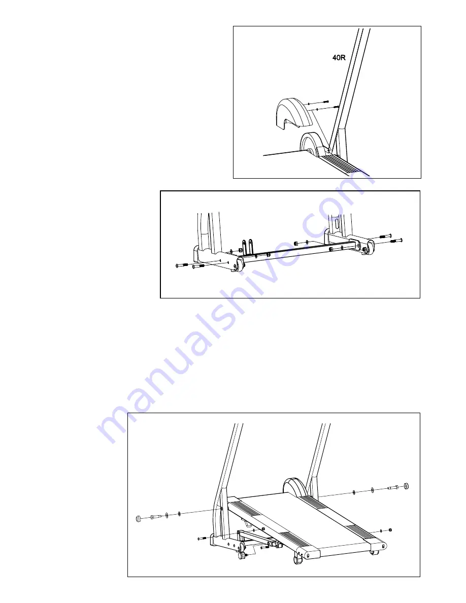
STEP 1

Fix the wheel cover (42) onto the main frame 

(1) with the screw (4), flat washer (5)

STEP 2 

Fix the base frame (33) 

onto the upright tube 

(40L/R) with the screw 

(16),flat  washer(18),nylon 

nut(19).

STEP 3

Fix the main frame (1) onto the upright tube (40L/R) with the bolt (37), Big flat washer (38), flat washer (39), 

then put on the round end cap (36).

Fix the adjustable tube (21) onto the base frame (33) with the screw (16), flat washer (18), nylon nut (19). 

Then fix the extended tube (17) onto the U shape of the main frame (1) with the screw (16), flat washer (18), 

nylon nut (19). And then connect the extended tube (17), adjustable tube (21) with the knob (15). .The adjust-

able pad (3) can be adjusted in three different angles to keep the Main frame(1) balance.

4

5

42

5

4

16

16

19

18

18 19

33

40L

40R

16

19

18

16

18 19

36

37 38

39

39

38

37

36

40L

40R

1

18 19

21

33

15

16 17

18

19

16

Summary of Contents for Magnetic Jog WITL11013.0

Page 1: ...ep this manual for future reference QUESTIONS If you have questions or if there are missing parts please contact us UK Call 08457 089 009 From Ireland 053 92 36102 Website www iconsupport eu E mail cs...

Page 2: ...OTING 13 EXERCISE GUIDELINES 14 EXPLODED DRAWINGS 16 PART LIST 18 ORDERING REPLACEMENT PARTS Last page WARNING DECAL PLACEMENT This drawing shows the location s of the warning decal s If a decal is mi...

Page 3: ...rear roller Adjust the roller guards if necessary 7 Keep children under the age of 12 and pets away from the treadmill at all times 8 The treadmill should not be used by persons weighing over 115 kg...

Page 4: ...number can be found on a decal attached to the treadmill see the front cover of this manual to find the location of the decal ASSEMBLY Assembly requires two persons Place all parts of the treadmill in...

Page 5: ...d end cap 36 Fix the adjustable tube 21 onto the base frame 33 with the screw 16 flat washer 18 nylon nut 19 Then fix the extended tube 17 onto the U shape of the main frame 1 with the screw 16 flat w...

Page 6: ...the computer back accordingly Then fix the com puter 32 onto the computer bracket of the handle bar 61 with the screw 64 Now your machine is ready for use HOW TO FOLD THE PRODUCT This treadmill can be...

Page 7: ...e careful to keep the walking belt centred 3 SYMPTOM THE WALKING BELT SLIPS OR IS OFF CENTRE a If the walking belt slips when walked on use the hex key to turn both adjustment bolts clockwise 1 4 of a...

Page 8: ...eet of clear plastic on the face of the console remove it 1 Turn on the console To turn on the console press any button on the console or simply begin pedaling 2 Press the buttons MODE Press this butt...

Page 9: ...body uses carbohydrate calories for energy Only af ter the first few minutes of exercise does your body begin to use stored fat calories for energy If your goal is to burn fat adjust the intensity of...

Page 10: ...45 47 46 45 44 4 5 41 42 43 21 15 16 4 5 6L 17 1 18 25 26 19 7 11 10 12 8 13 8 14 39 55 57 56 9 53 52 51 49 50 48 54 2 23 59 34 20 34 8 5 4 4 30 4 11 18 19 22 23 24 27 6R 58 61 39 10 11 29 11 22 20 1...

Page 11: ...oller Screw M6 12 Handle bar Screw ST4 20 Foam grip Screw Pulse sensor wire Qty 1 2 2 2 2 4 2 1 1 1 1 8 1 1 1 1 2 1 2 1 1 1 1 1 2 1 4 1 2 2 2 1 Item 1 2 3 4 5 6 7 8 9 10 11 12 13 14 15 16 17 18 19 20...

Page 12: ...ION FOR E U CUSTOMERS This electronic product must not be disposed of in municipal waste To preserve the environment this product must be recycled after its useful life as required by law Please use r...

Reviews: