background image

4

Thank you for selecting the new WESLO

®

PURSUIT

CT 1.5 exercise bike. Cycling is an effective exercise

for increasing cardiovascular fitness, building

endurance, and toning the body. The PURSUIT CT 1.5

exercise bike provides a selection of features

designed to make your workouts at home more effec-

tive and enjoyable.

For your benefit, read this manual carefully before

you use the exercise bike.

If you have questions

after reading this manual, please see the front cover

of this manual. To help us assist you, note the product

model number and serial number before contacting

us. The model number and the location of the serial

number decal are shown on the front cover of this

manual.

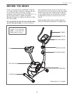
Before reading further, please review the drawing

below and familiarize yourself with the labeled parts.

Resistance Knob

Water Bottle Holder*

Seat

Seat Post Knob

Pedal/Strap

Leveling Cap

Console

Heart Rate Monitor

Handlebar

BEFORE YOU BEGIN

*Water bottle is not included

Length: 2 ft. 9 in. (84 cm)

Width: 1 ft. 8 in. (51 cm)

Weight: 66 lbs. (30 kg)

Meijer.com

Summary of Contents for pursuit CT 1.5

Page 1: ...ber in the space above for reference www weslo com QUESTIONS If you have questions or if parts are damaged or missing DO NOT CONTACT THE STORE please contact Customer Care IMPORTANT Please register this product see the limited warranty on the back cover of this manual before contacting Customer Care CALL TOLL FREE 1 866 699 3756 Mon Fri 6 a m 6 p m MT Sat 8 a m 4 p m MT ON THE WEB www wesloservice...

Page 2: ...18 EXPLODED DRAWING 19 ORDERING REPLACEMENT PARTS Back Cover LIMITED WARRANTY Back Cover WESLO is a registered trademark of ICON IP Inc WARNING DECAL PLACEMENT This drawing shows the location s of the warning decal s If a decal is missing or illegible see the front cover of this manual and request a free replacement decal Apply the decal in the location shown Note The decal s may not be shown at a...

Page 3: ...nce around the exercise bike To protect the floor or carpet from damage place a mat under the exercise bike 7 Inspect and properly tighten all parts regu larly Replace any worn parts immediately 8 Keep children under age 12 and pets away from the exercise bike at all times 9 Wear appropriate clothes while exercising do not wear loose clothes that could become caught on the exercise bike Always wea...

Page 4: ...ons after reading this manual please see the front cover of this manual To help us assist you note the product model number and serial number before contacting us The model number and the location of the serial number decal are shown on the front cover of this manual Before reading further please review the drawing below and familiarize yourself with the labeled parts Resistance Knob Water Bottle ...

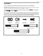
Page 5: ...nd pliers See the drawings below to identify the small parts needed for assembly The number in parentheses below each drawing is the key number of the part from the PART LIST near the end of this manual The number following the key number is the quantity needed for assembly Note If a part is not in the hardware kit check to see if it has been preassembled To avoid damaging parts do not use power t...

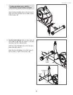
Page 6: ... and the cardboard tube from the Frame 1 Discard the screw and the cardboard tube Orient the Front Stabilizer 2 so that the large holes face the Frame 1 Attach the Front Stabilizer 2 to the Frame 1 with two M10 x 70mm Patch Screws 33 1 1 2 33 2 Large Holes To make assembly easier read the information on page 5 before you begin 1 Screw Cardboard Tube Meijer com ...

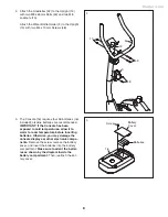
Page 7: ...side the metal bracket See drawing B Firmly pull the Resistance Cable 19 upward and slide it into the top of the metal bracket See drawing C Using pliers squeeze the prongs on the upper end of the metal bracket together Insert the wires and cables downward into the Frame 1 Tip Avoid pinching the wires and cables Insert the Upright 13 into the Frame 1 Attach the Upright 13 with three M8 x 15mm Patc...

Page 8: ...ectronic compo nents Remove the screw remove the battery cover and insert the batteries into the battery compartment Make sure to orient the batter ies as shown by the diagram inside the battery compartment Then reattach the bat tery cover 5 Batteries Screw Battery Cover 16 4 4 Attach the Handlebar 42 to the Upright 13 with two M8 x 65mm Bolts 49 and two M8 Locknuts 10 Attach the Water Bottle Hold...

Page 9: ...excess wire into the Upright 13 or into the Console 16 Tip Avoid pinching the wires Attach the Console 16 to the Upright 13 with four M4 x 15mm Screws 48 48 16 13 23 7 Attach the Seat 12 to the Seat Post 5 with four M8 Locknuts 10 Note The Locknuts may be preattached to the underside of the Seat 5 10 12 Avoid pinching the wires Meijer com ...

Page 10: ...t shown Adjust the strap on the Left Pedal 24 to the desired position and press the end of the strap onto the tab on the side of the Left Pedal Adjust the strap on the Right Pedal not shown in the same way 9 24 Strap Tab 21 8 Loosen and remove the Seat Post Knob 9 from the Frame 1 Insert the Seat Post 5 into the Frame 1 Adjust the Seat Post to the desired height and insert the Seat Post Knob 9 thr...

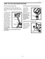
Page 11: ... into the frame and the seat post and then tighten the seat post knob Make sure that the seat post knob is inserted through one of the adjustment holes in the seat post HOW TO ADJUST THE PEDALING RESISTANCE To increase the resistance of the pedals turn the resistance knob clockwise to decrease the resis tance turn the knob counterclockwise IMPORTANT Stop turning the knob when turning becomes diffi...

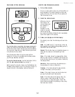
Page 12: ...rn on the console the manual mode will be selected If you have selected a pace workout reselect the manual mode by pressing the Workout Select button repeatedly until zeros appear in the display 3 Follow your progress with the display The display can show the following workout infor mation RPM The RPM meter on the left side of the dis play indicates your approximate pedaling pace in revolutions pe...

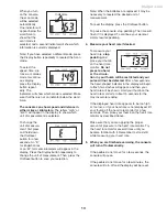
Page 13: ...the display press the On Reset button To pause the console stop pedaling The time will flash if it is displayed To continue your workout simply resume pedaling 4 Measure your heart rate if desired To measure your heart rate stop pedaling and place your thumb on the heart rate monitor Do not press too hard or the circula tion in your thumb will be restricted and your pulse will not be detected Afte...

Page 14: ... During the work out the pace guide will prompt you to keep your pedaling speed near the target pace for the current segment When the left indica tor lights increase your speed when the right indicator lights decrease your speed When the center indicator lights maintain your current speed IMPORTANT The pace guide is intended only to provide a goal Make sure to pedal at a speed that is comfortable ...

Page 15: ...should be adjusted To adjust the reed switch the left pedal and the left shield must be removed Using an adjustable wrench turn the left pedal clock wise and remove it Next remove all of the screws from both shields there are two sizes of screws in the shields note which size of screw you remove from each hole Then carefully remove the left shield Turn the resistance knob to the lowest setting The...

Page 16: ...radio TV technician for help FCC CAUTION To assure continued compliance use only shielded interface cables when connecting to computer or peripheral devices Changes or modifications not expressly approved by the party respon sible for compliance could void the user s authority to operate this equipment HOW TO ADJUST THE DRIVE BELT If you can feel the pedals slip while you are pedaling even when th...

Page 17: ...to strengthen your cardiovascular system you must perform aerobic exercise which is activity that requires large amounts of oxygen for prolonged periods of time For aerobic exercise adjust the intensity of your exercise until your heart rate is near the highest number in your training zone WORKOUT GUIDELINES Warming Up Start with 5 to 10 minutes of stretching and light exercise A warm up increases...

Page 18: ...le 30 4 M8 x 60mm Patch Screw 31 2 Eyebolt 32 2 M6 Locknut 33 2 M10 x 70mm Patch Screw 34 3 M8 x 15mm Patch Screw 35 1 Drive Belt 36 1 Crank Bearing Set 37 1 Flywheel 38 2 Magnet 39 1 Reed Switch Wire 40 1 M8 x 20mm Bolt 41 7 M4 x 25mm Screw 42 1 Handlebar 43 3 Flywheel Nut 44 1 M5 x 50mm Button Screw 45 1 M8 Washer 46 6 M4 x 15mm Button Screw 47 1 M5 x 15mm Screw 48 7 M4 x 15mm Screw 49 2 M8 x 65...

Page 19: ... 30 29 9 31 32 37 38 28 31 32 28 11 1 33 46 22 39 20 5 12 21 24 26 36 34 48 8 27 6 43 23 47 41 14 14 4 8 44 43 43 45 25 10 40 10 42 38 3 41 46 46 41 15 48 48 49 13 46 10 50 50 EXPLODED DRAWING Model No WLEX31310 1 R0112A Meijer com ...

Page 20: ...s warranty will automatically be voided if the product is used as a store display model if the product is purchased or transported outside the USA if all instructions in this manual are not followed if the product is abused or improperly or abnormally used or if the product is used for commercial or rental purposes No other war ranty beyond that specifically set forth above is authorized by ICON I...

Reviews: