background image

12

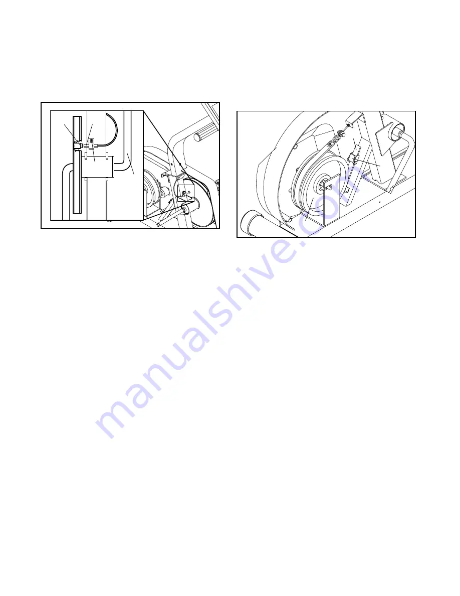
HOW TO ADJUST THE REED SWITCH

If the console does not display correct feedback, the
reed switch may need to be adjusted. To adjust the
reed switch, you must first remove the left side shield
(see HOW TO REMOVE THE LEFT SIDE SHIELD on
page 11).

With the left side shield removed, locate the Reed
Switch (42). Turn the Crank (8) until the Magnet (61)
is aligned with the Reed Switch. Loosen, but do not
remove, the M4 x 16mm Screw (43). Slide the Reed
Switch slightly closer to or farther away from the
Magnet. Retighten the Screw. Turn the Crank for a
moment. Repeat until the console displays correct
feedback. When the Reed Switch is correctly adjust-
ed, reattach the left side shield and the left pedal.

HOW TO ADJUST THE RESISTANCE STRAP

If the resistance knob is set on its highest setting and
there is not enough resistance, the resistance strap
may need to be adjusted. To adjust the resistance
strap, you must first remove the left side shield (see
HOW TO REMOVE THE LEFT SIDE SHIELD on
page 11).

With the left side shield removed, turn the resistance
knob to the lowest setting (see HOW TO ADJUST
THE PEDALING RESISTANCE on page 9). Open the
Strap Clamp (57) and pull the end of the Resistance
Strap (41) slightly upward to increase resistance.
Close the Strap Clamp and turn the Flywheel (15) to
make sure that there is not too much resistance.
When the Resistance Strap is properly adjusted, re-
attach the left side shield and the left pedal.

42

61

43

8

Rear
View

57

15

41

Summary of Contents for Pursuit E21

Page 1: ...rantee complete satisfaction through direct assistance from our factory TO AVOID DELAYS PLEASE CALL DIRECT TO OUR TOLL FREE CUSTOMER HOT LINE The trained technicians on our cus tomer hot line will provide imme diate assistance free of charge to you CUSTOMER HOT LINE 1 800 999 3756 Mon Fri 6 a m 6 p m MST Model No WLEX14020 Serial No Patent Pending Write the serial number in the space above for ref...

Page 2: ...IN 4 ASSEMBLY 5 HOW TO USE THE EXERCISE CYCLE 9 MAINTENANCE AND STORAGE 11 CONDITIONING GUIDELINES 13 PART LIST 14 EXPLODED DRAWING 15 ORDERING REPLACEMENT PARTS Back Cover LIMITED WARRANTY Back Cover WESLO is a registered trademark of ICON Health Fitness Inc ...

Page 3: ...thing that could become caught on the exercise cycle Always wear athletic shoes when using the exercise cycle 8 Always keep your back straight when using the exercise cycle Do not arch your back 9 If you feel pain or dizziness while exercising stop immediately and begin cooling down 10 The pulse sensor is not a medical device Various factors including the user s move ment may affect the accuracy o...

Page 4: ... Customer Service Department toll free at 1 800 999 3756 Monday through Friday 6 a m until 6 p m Mountain Time excluding holidays To help us assist you please mention the product model number and serial number when calling The model number is WLEX14020 The serial number can be found on a decal attached to the exercise cycle see the front cover of this manual for the location of the decal Before re...

Page 5: ...h drawing refers to the key number of the part from the PART LIST on page 14 the second number refers to the quantity needed for assembly Note Some small parts may have been pre attached for shipping If a part is not in the parts bag check to see if it has been pre assembled M8 Flat Washer 51 8 M10 x 70mm Carriage Bolt 27 2 M4 x 16mm Screw 43 4 M10 x 97mm Hex Head Bolt 12 2 M8 x 66mm Carriage Bolt...

Page 6: ...e Cable 31 up through the Upright Attach the Upright with three M10 x 25mm Button Head Screws 53 and three M10 Split Washers 54 Be careful not to pinch the Reed Switch Wire or the Resistance Cable 1 2 3 54 54 53 53 31 3 42 4 The Console 33 requires two AA batteries not included alkaline batteries are recommended Open the battery door on the back of the Console Press two batteries into the Console ...

Page 7: ...exercise cycle on its side to attach the Seat Upright 11 11 64 2 55 51 51 55 6 5 3 42 22 69 33 32 43 43 31 5 Connect the Reed Switch Wire 42 to the corre sponding console wire Attach the ground wire to the Upright 3 with an M4 x 8mm Screw 22 Connect the Pulse Wires 69 to the corresponding console wires Insert the excess wire into the Upright Attach the Console 33 to the Upright 3 with four M4 x 16...

Page 8: ...M6 x 16mm Screws 46 8 45 46 64 11 12 63 25 26 10 10 Attach the Seat Handles 25 to the Seat Bracket 63 with two M10 x 97mm Hex Head Bolts 12 and two M10 Nylon Locknuts 26 9 Attach the Seat 44 to the Seat Bracket 63 with four M6 x 16mm Screws 46 44 63 46 9 12 25 ...

Page 9: ...e Console 33 To increase the resistance turn the Resistance Knob clockwise to decrease the resistance turn the Resistance Knob counterclockwise Tab 67 32 33 29 2 8 68 12 13 Make sure that all parts are properly tightened before you use the exercise cycle Note There may be some hardware left over after assembly is completed 9 12 Identify the Left Pedal 39 there is an L on the Left Pedal for identif...

Page 10: ...s the on reset button or simply begin pedaling When the power is turned on the entire display will appear for two seconds The console will then be ready for operation 2 Select one of the six modes Scan mode When the power is turned on the scan mode will automatically be selected One mode arrow will show that the scan mode is selected and a flashing mode arrow will show which mode is cur rently dis...

Page 11: ...eaned with a soft damp cloth To prevent damage to the console keep liquids away from the console and keep the console out of direct sunlight BATTERY REPLACEMENT If the console does not function properly the batteries should be replaced See assembly step 4 on page 6 CRANK ADJUSTMENT If the arms of the Crank 8 become loose they should be tightened in order to prevent exces sive wear Loosen the Hex C...

Page 12: ...ctly adjust ed reattach the left side shield and the left pedal HOW TO ADJUST THE RESISTANCE STRAP If the resistance knob is set on its highest setting and there is not enough resistance the resistance strap may need to be adjusted To adjust the resistance strap you must first remove the left side shield see HOW TO REMOVE THE LEFT SIDE SHIELD on page 11 With the left side shield removed turn the r...

Page 13: ...exercise must be aerobic Aerobic exercise is activity that requires large amounts of oxygen for prolonged periods of time This increases the demand on the heart to pump blood to the muscles and on the lungs to oxygenate the blood For aerobic exercise adjust the intensity of your exercise until your heart rate is near the highest number in your training zone WORKOUT GUIDELINES Each workout should i...

Page 14: ...knut 27 2 M10 x 70mm Carriage Bolt 28 2 Foam Grip 29 1 Frame Knob 30 1 Stabilizer 31 1 Resistance Control Cable 32 1 Resistance Knob 33 1 Console 34 2 Stabilizer Endcap 35 2 Seat Frame Bushing 36 1 Frame Bushing 37 1 Handlebar 38 1 Right Pedal 39 1 Left Pedal 40 1 J Bolt 41 1 Resistance Strap 42 1 Reed Switch w Wire 43 9 M4 x 16mm Screw 44 1 Seat 45 1 Backrest 46 8 M6 x 16mm Screw 47 2 2 x 3 Endca...

Page 15: ...1 43 42 9 8 39 14 9 18 22 18 22 36 29 61 41 8 7 38 47 52 55 11 11 43 43 46 46 2 55 64 44 45 27 24 24 55 26 26 26 12 25 25 66 33 32 53 54 53 54 3 42 69 57 43 31 56 62 48 13 51 51 51 51 67 68 5 5 46 46 10 40 50 26 4 49 50 55 55 17 16 15 60 19 55 58 59 58 59 60 12 13 13 69 53 37 54 54 22 35 ...

Page 16: ...oduct caused by or attributable to freight damage abuse mis use improper or abnormal usage or repairs not provided by an ICON authorized service center products used for commercial or rental purposes or products used as store display models No other warranty beyond that specifically set forth above is authorized by ICON ICON is not responsible or liable for indirect special or consequential damage...

Reviews: