background image

6

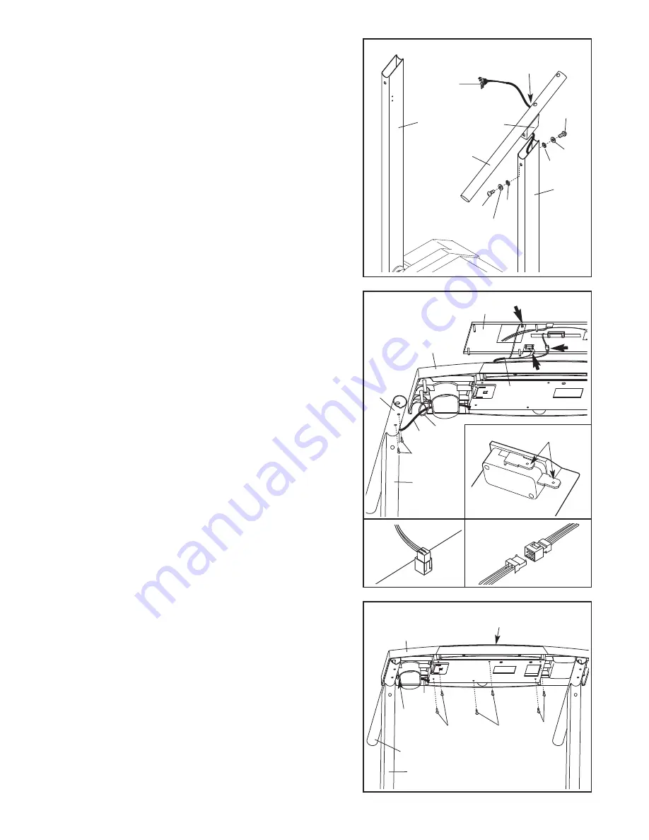
3. With the help of a second person, position the treadmill

with the Uprights (14, 15) in the vertical position as
shown. Hold one of the Handrails (4) near the Right
Upright (15).

Route the Wire Harness (53) through the bracket on the
Handrail (4) and out the large hole on the side of the
Handrail. Insert the bracket on the Handrail into the top
of the Right Upright (15). Attach the Handrail with two 1”
Bolts (16), two 1/4” Washers (32), and two 1/4” Star
Washers (7) as shown. 

Do not tighten the Bolts yet.

Attach the Left Handrail (not shown) as described above.
Note: There is not a wire harness on the left side.

4. Hold the Console Base (87) and the Console (11) near the

Right Upright (15). Insert the Wire Harness (53) through
the indicated plastic tie on the Console Base and up
through the hole in the Console Base. Remove the tape
from ends of the small wires in the Wire Harness. Set the
Console Base onto the Handrails (4). Attach the Console
Base with four 3/4” Screws (5) (only two Screws are
shown). 

Start all four Screws before tightening them.

Touch the right Handrail (4) to discharge any static.

Locate the two wires in the Wire Harness (53) that have
L-shaped connectors on the ends. Press the connectors
onto the two tabs on the switch shown in inset drawing 4a. 

Connect the other two wires in the Wire Harness (53) to
the back of the Console (11) in the locations shown by
the arrows in drawing 4. 

The connectors should slide

easily into the sockets and snap into place 

(see draw-

ings 4b and 4c). If the connectors do not slide easily and
snap into place, turn the connectors and then insert
them. 

IF THE CONNECTORS ARE NOT INSERTED

PROPERLY, THE CONSOLE MAY BE DAMAGED
WHEN THE POWER IS TURNED ON.

Large

Hole

Bracket

4

15

53

14

4

Tie

11

3

32

32

7

7

16

16

87

4

53

53

15

5

Tabs

4a

4b

4c

87

11

Tie

4

5

5. Set the Console (11) into the Console Base (87). 

Make

sure that no wires are pinched. 

Attach the Console to

the Console Base with six 3/4” Screws (5) in the locations
shown. 

Start all six Screws before tightening them.

Insert any extra Wire Harness (53) into the right Handrail
(4) and right Upright (15). 

Securely tighten the plastic

tie to prevent the Wire Harness from slipping.

Then,

cut off the end of the plastic tie.

15

53

5

5

5

Summary of Contents for Sport 350 Treadmill

Page 1: ...reference Visit our website at www weslo com new products prizes fitness tips and much more QUESTIONS As a manufacturer we are com mitted to providing complete customer satisfaction If you have quest...

Page 2: ...Wear appropriate exercise clothes when using the treadmill Do not wear loose clothes that could become caught in the treadmill Athletic support clothes are recommended for both men and women Always w...

Page 3: ...rly assembled See ASSEMBLY on page 5 and HOW TO FOLD AND MOVE THE TREADMILL on page 12 You must be able to safely lift 45 pounds 20 kg to raise lower or move the treadmill 20 When folding or moving th...

Page 4: ...you note the product model number and serial number before calling The model number of the treadmill is WLTL33205 0 The serial number can be found on a decal attached to the tread mill see the front...

Page 5: ...e Do not fully fold the treadmill until it is completely assembled Attach four Base Pads 33 to the Base 38 with four 3 4 Tek Screws 31 Attach a Wheel 42 to the right side of the Base with a Wheel Bolt...

Page 6: ...s before tightening them Touch the right Handrail 4 to discharge any static Locate the two wires in the Wire Harness 53 that have L shaped connectors on the ends Press the connectors onto the two tabs...

Page 7: ...l 5 66 14 7 7 7 Attach the Storage Latch 66 to the Left Upright 14 with two 3 4 Screws 5 Be careful not to overtighten the Screws 6 Lower the Uprights 14 15 until the Handrails 4 are touching the floo...

Page 8: ...lfunc tion or break down grounding provides a path of least resistance for electric current to reduce the risk of elec tric shock This product is equipped with a cord having an equipment grounding con...

Page 9: ...n below Press two batteries into the battery com partment Make sure that the neg ative ends of the batteries are touching the springs Close the battery cover STEP BY STEP CONSOLE OPERATION If there is...

Page 10: ...gn it if necessary see page 14 Monitor your progress with the two displays TIME DISTANCE dis play This display shows the elapsed time and distance that you have walked or run in miles Every seven seco...

Page 11: ...s shown below Adjust the in cline leg to the desired height and fully reinsert the in cline pin Make sure that the incline pin is in the locked position shown in the inset drawing Adjust the other inc...

Page 12: ...atures above 85 Fahrenheit HOW TO MOVE THE TREADMILL Before moving the treadmill convert the treadmill to the storage position as described above Make sure that the storage latch is fully engaged over...

Page 13: ...ff during use SOLUTION a Check the circuit breaker located on the treadmill frame near the power cord see the drawing above If the circuit breaker has tripped wait for five minutes and then press the...

Page 14: ...er or slips when walked on SOLUTION a If the walking belt is off center first remove the key and UNPLUG THE POWER CORD If the walking belt has shifted to the left use the allen wrench to turn the left...

Page 15: ...ncreases the demand on the heart to pump blood to the muscles and on the lungs to oxygenate the blood For aerobic exercise adjust the speed and incline of the treadmill until your heart rate is near t...

Page 16: ...heel Nut 43 2 3 4 Screw 5 12 1 Bolt 16 4 2 1 2 Bolt 10 4 3 4 Tek Screw 31 4 Wheel Bolt 41 2 Remove this chart and use it to identify small parts during assembly Save this chart and the EXPLODED DRAWIN...

Page 17: ...t 41 2 Wheel Bolt 42 2 Wheel 43 3 Motor Pivot Nut Wheel Nut 44 2 Base Endcap 45 1 Circuit Breaker 46 1 Grommet 47 1 Power Cord 48 1 Motor Tension Nut 49 1 Console Cover 50 2 Right Rail 51 4 Platform S...

Page 18: ...72 65 8 78 32 46 47 51 51 71 1 1 39 58 58 39 86 73 80 77 56 28 29 28 28 28 5 17 4 4 73 17 5 61 5 87 55 12 64 41 42 43 33 31 42 43 41 33 31 76 35 76 18 43 26 24 19 20 21 48 76 85 37 19 76 57 38 53 44 9...

Page 19: ...rip charge This warranty does not extend to any product or damage to a product caused by or attributable to freight damage abuse misuse im proper or abnormal usage or repairs not provided by an ICON a...

Reviews: