


7
10
7
3
24
40
24
8
4
70
Console
Wires
69
Pulse
Wires
Earthed
Wire
5
3
55
55
7
58
58
Pulse
Wires
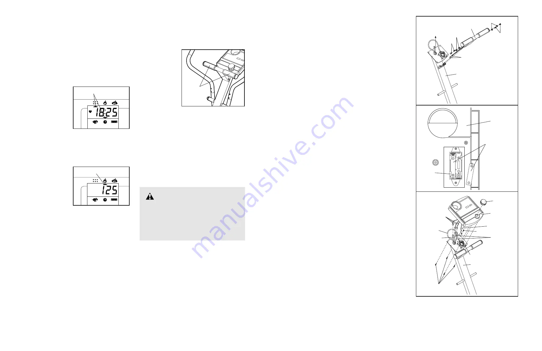
HOW TO OPERATE THE CONSOLE
Note: The console requires two 1.5V batteries. See
assembly step 6 on page 7 for battery installation
instructions.
1. To turn on the power, press the on/reset button or
simply begin pedalling. When the power is turned
on, the entire display will appear for two seconds.
The console will then be ready for operation.
2. Select one of the six modes:
Scan mode—
When the power
is turned on, the
scan mode will
automatically be
selected. One
mode arrow will
show that the
scan mode is
selected, and a
flashing mode arrow will show which mode is cur-
rently displayed. Note: If a different mode is select-
ed, you can select the scan mode again by repeat-
edly pressing the mode button.
Speed, time, dis-
tance, fat calo-
ries, or calories
mode— To select
one of these
modes for contin-
uous display,
press the mode
button repeatedly.
The mode arrows will show which mode is select-
ed. Make sure that the scan mode is not selected.
3. To reset the display, press the on/reset button.
4. To turn off the power, simply wait for a few minutes.
Note: The monitor has an “auto-off” feature. If
the pedals are not moved and the monitor but-
tons are not pressed for a few minutes, the
power will turn off automatically in order to
conserve the batteries.
HOW TO USE THE PULSE SENSOR
Note: Before using the pulse sensor, peel the pro-
tective vinyl covering off the metal contacts on
the top and bottom of the pulse sensor.
To use the pulse
sensor, place
your hands on
the metal con-
tacts. Your
palms must be
resting on the
upper contacts
and your fingers
must be touch-
ing the lower
contacts. Avoid
moving your hands.
After a moment, the heart-shaped indicator in the dis-
play will begin to flash, three dashes (– – –) will
appear, and then your heart rate will be shown. For
the most accurate heart rate reading, continue to hold
the contacts for about 15 seconds.
Note: If your heart rate is not shown, press the
on/reset button to reset the display. In addition,
make sure that your hands are positioned as
described above. Be careful not to move your hands
excessively or squeeze the metal contacts too tightly.
Mode Arrows
Metal
Contacts
WARNING:
The pulse sensor
is not a medical device. Various factors,
including the user's movement, may affect
the accuracy of heart rate readings. The
pulse sensor is intended only as an exer-
cise aid in determining heart rate trends in
general.
7. Connect the Extension Wire (40) and the two pulse
wires to the corresponding wires on the Console (4).
If your Console (4) has an earthed wire, attach it to
the Upright (3) with an M4 x 10.5mm Screw (70).
Insert any excess wiring down into the Upright (3).
Do not push the Upper Cable (24) down into the
Upright.
Next, attach the Console (4) to the Upright (3) with
four Console Screws (69).
Press the Resistance Knob (8) onto the Resistance
Control (24). Make sure that the mark on the
Resistance Knob is correctly aligned.
6. The Console (4) requires two 1.5V batteries.
Alkaline batteries are recommended.
To install batteries, first locate the battery clip under
the Console (4). Insert two batteries into the battery
clip as shown. Make sure that the batteries are
turned so the negative ends of the batteries
(marked “–”) are touching the springs in the
battery clip.
5. Route both pulse wires up through the Upright (3) as
shown.
Attach the T-bar (7) to the Upright (3) with four M6 x
16mm Button Screws (55) and four M6 Split
Washers (58).
4
6
Batteries
Battery
Clip
Mode Arrow


