I
N
M
E
G
30
F
4
9
6
28
96
29
17
14
15
29 17
7
R
7
L
32
15
14
6
L
6
L
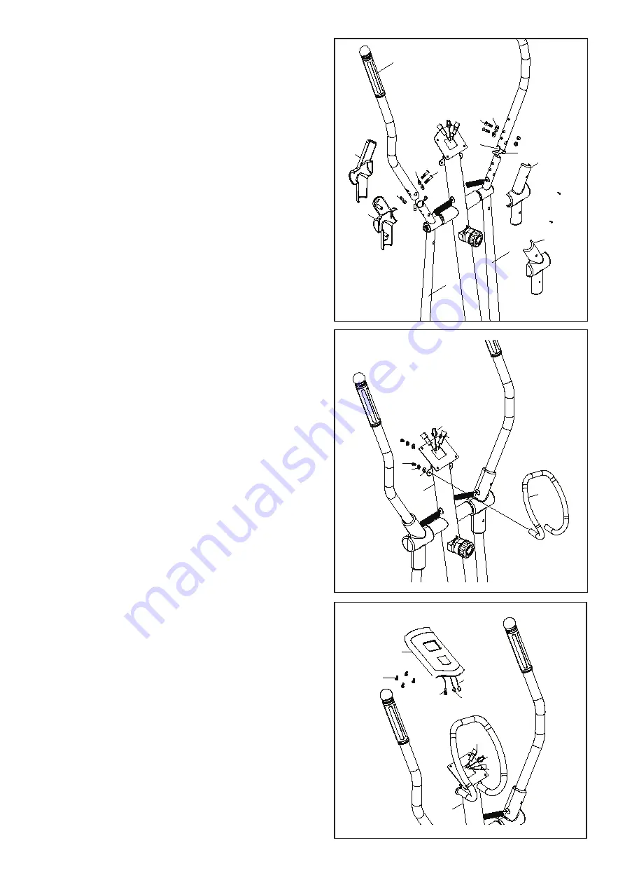
STEP 6 Upper and lower swing bars
Take the left upper swing bar (7L) close to the left lower
swing bar (6L) and then connect the hand pulse wire1
(96) and the hand pulse wire 2(28)
Insert the left upper swing bar (7L) into the left lower
swing bar (6L); Insert M8*36 inner hexagon screw (29)
through the M8 arch washer (17) and the upper & lower
swig bars. Lock them up with M8 nylon cap (32). Cover
this joint place with swing bar housing 1 (14) and swing
bar housing 2 (15) from front and rear direction. And
finally use M4*35 round cross screw (42) to lock it tight.
NOTE: The right upper swing bar (7R) assembly way is
exactly the as the left upper swing bars.
STEP 7 Handle bar :
Move the handle bar (8) close to the meter post (4);
Insert the hand pulse wire E, G from the handle bar (8)
through the hole on the back side of the meter post; pull
the hand pulse wire E, G out of the top site of the meter
post. Lock the handle bar (8) to the meter post (4) with
M8*20 inner hexagon screw (19), M8 spring washer
(23), M8 arch washer (17).
Connect the hand pulse wire EG, then connect with wire
which come out from computer post(see picB)
- First remove the M8*20 flat cross screw (19), M8
spring washer (23) and OD20*ID8.5*1.5T flat washer
(17) which were pre-assembled on the round bar (8).
- Attach the round bar to the top site of the meter post
and use the removed screws & washers to lock it up.
STEP 8 Meter :
Remove the M5*12 meter screws (30) which are pre-
assembled on the back side of the meter (9); Connect
the sensor wire F out from the meter post (4) with the
sensor wire I out from meter (9); connect the hand pulse
wire E, G out from meter post with the sensor wire M,
N out from meter. Attach the meter closely to the mete
post and lock them tight with the removed screw.
4
E
G
8
23
19
17


