


Page 51
WESMAR
INSTALLATION AND OPERATION
Route the soundome cable through the left large strain
relief in the bottom of the Junction Box.
Connect the numbered lugs of the soundome cable to
the same numbered terminals on the Hoist Board in
the Junction Box.
In addition to the numbered wires, there is one wire,
brown in color, labeled "GND", inside the J-box. This
brown wire is connected to the ground post at the
bottom of the J-box.
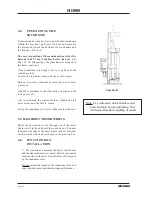
9.0
LEAD SCREW HOIST
OPERATION
CHECK
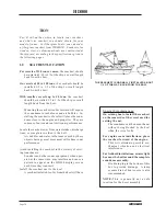
6-Inch Soundome:
Total travel distance up or down
is 20.3 cm (8 inches). See Page 55, #5.
8-Inch Soundome:
Total travel distance up or down
is 28.0 cm (11 inches). See Page 55, #5.
The hoist motor is calibrated at the factory for
correct travel distance, but you should check it
after installation. Incorrect travel distance means
your soundome may not be going low enough into
the water to allow the soundbeam full clearance.
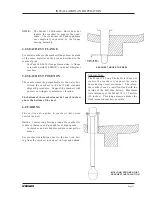
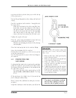
Tighten the packing gland only until it slightly weeps
water.
A packing gland that is too tight will create
excess friction on the soundome tube. This fric-
tion may cause damage to the hoist motor or
blow the hoist fuse on the hoist board.
9.1
Hoist Operation Check Procedure
To check hoist travel, follow these steps before returning
your vessel to the water:
Summary of Contents for HD800/110-10
Page 10: ...Page 10 WESMAR HD800...
Page 32: ...Page 32 WESMAR HD800 Section III INSTALLATION...
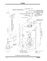
Page 64: ...Page 64 WESMAR HD800 HYDRAULIC HOIST ASSEMBLY A...
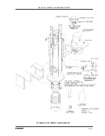
Page 65: ...Page 65 WESMAR INSTALLATION AND OPERATION HYDRAULIC HOIST ASSEMBLY B...
Page 74: ...Page 74 WESMAR HD800 M18 HOIST CONTROL CIRCUITRY THIS PAGE LEFT INTENTIONALLY BLANK...
Page 86: ...Page 86 WESMAR HD800...
Page 87: ...Page 87 WESMAR INSTALLATION AND OPERATION Section IV FIELD ADJUSTMENTS CALIBRATION...
Page 92: ...Page 92 WESMAR HD800 HD J BOX TRANSMIT PREAMP RECEIVER PCB T P R...