


Page 83
WESMAR
INSTALLATION AND OPERATION
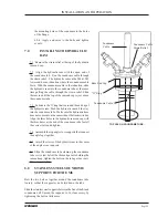
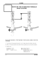
19.1.5 When performing the next steps, do not let
the hoist descend so far that the motor continues
to run after it touches the lower stop.
This could damage the hoist assembly.
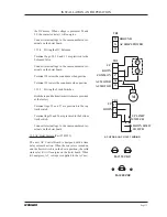
19.1.6 Make sure leads from Terminal 2 and Ter-
minal 27 are not touching any other wire.
Turn on the hoist and console, and push down the
hoist switch.
Now there is +12VDC on the wire you pulled from
Terminal 2, and hoist motor voltage.
19.1.7 When voltage is applied to the hoist, check
the hoist down light on the console. It should be off.
Move the hoist motor in small steps by tapping the
12VDC wire to Terminal 2 until the motor stops
driving.
Do not let the tube clamp press into the shock tube.
19.1.8 When the hoist stops, there must be at least
1.25 cm (.5 inch) between the tube clamp and
packing gland.
19.1.9 If the safety clamp does not stop, or if it is
less than 1.25 cm (.5 inches) above the packing
gland, you must reposition the bottom limit switch.
Check the "hoist down" light on the console. The
red light should be on.
20.0 TROUBLESHOOTING
20.1 Motor runs, but will not raise or lower hoist:
~
Solenoid valve stuck
~
Fluid level of reservoir is too low
~
Solenoid valve is not properly con-
nected
to hoist board
~
Packing gland cap is too tight
~
Rack was bent during installation
Summary of Contents for HD800/110-10
Page 10: ...Page 10 WESMAR HD800...
Page 32: ...Page 32 WESMAR HD800 Section III INSTALLATION...
Page 64: ...Page 64 WESMAR HD800 HYDRAULIC HOIST ASSEMBLY A...
Page 65: ...Page 65 WESMAR INSTALLATION AND OPERATION HYDRAULIC HOIST ASSEMBLY B...
Page 74: ...Page 74 WESMAR HD800 M18 HOIST CONTROL CIRCUITRY THIS PAGE LEFT INTENTIONALLY BLANK...
Page 86: ...Page 86 WESMAR HD800...
Page 87: ...Page 87 WESMAR INSTALLATION AND OPERATION Section IV FIELD ADJUSTMENTS CALIBRATION...
Page 92: ...Page 92 WESMAR HD800 HD J BOX TRANSMIT PREAMP RECEIVER PCB T P R...


