
15
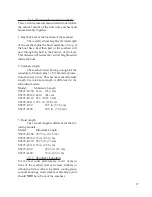
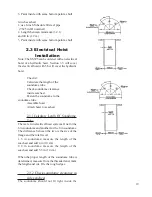
make a hole in the instrument panel 1 3/4 inches
(44.5 mm) in diameter. Attach the bulkhead con-
nector plate to the instrument pnael using the holes
in the four corners.
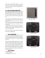
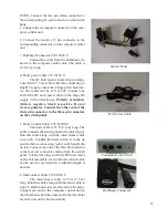
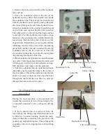
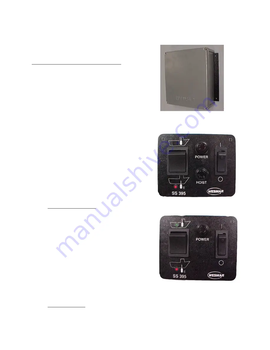
2.1.3 Computer Control Unit
The computer control unit is designed to fit under
the instrument panel. There are three cables in the
wheelhouse that connect to the computer control
unit. Consider the length of these cables before
selecting a lcoation to mount the computer control
unit.
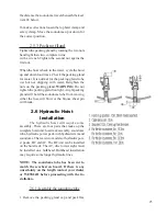
1. The cable from the bulkhead connector panel is
10ft ( 3 meters) long. it must reach the computer
control unit.
2. The AC power cable from the switch panel is
6 ft (1.8 meters) long. It must reach the computer
control unit.
3. The monitor video cable on most monitors is
normally short. Use an extension VGA cable to
reach the computer control unit if needed. (Exten-
sion cable not supplied).
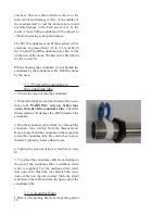
Fasten the computer control unit in place using the
holes in the mounting plate.
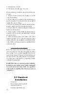
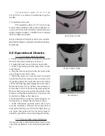
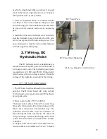
2.1.4 Switch Panel
There are two switch panel assemblies, one for
a lead screw hoist and the other for a hydraulic
hoist. Installation is the same for both. The switch
panel does not need to be next to the bulkhead
connector.
Switch panels for both the hydraulic hoist and the
lead screw hoist are the same size. They provide
power to the computer control unit through a 6ft
(1.8 meter) cable. This cable must reach the com-
puter control unit. Make a hole 2.5 X 2.5
inches
(63.5 X 63.5 mm). Pass the wires through the
hole and attach the plate by the four corners to the
instrument panel.
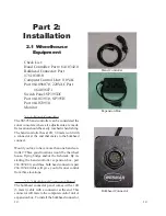
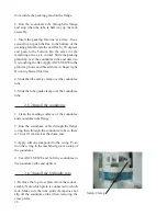
2.1.5 Monitor
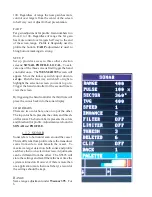
Specifications:
1. VGA, 640 X 480
2. Horizontal Sync. 31.5 kHz
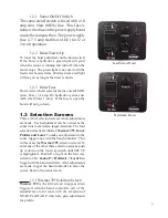
Computer Control
Lead Screw Hoist
Hydraulic Hoist
Summary of Contents for SS395
Page 36: ...36...