


32
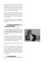
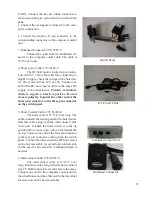
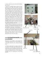
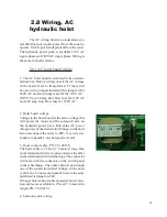
The solenoid valve is pre-wired with terminal lugs
at the ends. Run the solenoid cable through one of
the strain relief fittings on the hoist box. Connec
the wires to TB2, number to number.
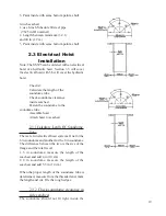
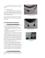
5. Limit switch up/down wiring:
There are two limit switches on the hoist rack that
will stop the hoist at the travel limits. Both swtiches
are pre-wired with terminal lugs at the ends. Run
the limit switch wires through on of the strain relief
fittings on the hoist box. Connect the wires to TB4,
number to number.
2.9 Operation check,
hydraulic hoist, DC & AC
2.9.1 Lowering hoist first time
1. Check to make sure there is enough room be-
neath the boat before lowering the soundome. Total
travel is 18 inches, 45.5cm. Outside the seachest
16.5 inches, 42cm.
2. Make sure the hoist switch is in the up posi-
tion.
3. Disconnect the upper hoist limit switch wire
labeled #27 located on, TB2 for DC motors or TB4
for AC motors. Once this wire is disconnected the
hoist will only move down when powered.
4. Disconnect the hoist down limit switch wire la-
beled #1 located on, TB1 for DC motors and TB1
for AC motors. Once this wire is disconnected
the hoist will not move when the hoist switch
in the wheelhouse is pushed down to lower the
soundome.
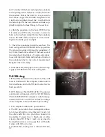
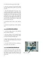
5. 1. The hoist will lower. The hoist should stop
before the safty clamp comes in contact with the
packing gland. If it looks like the safety clamp will
come in contact with the packing gland remove
the wire immediately. Tap the wire on terminal #1
for short movements until the hoist stops. The top
clamp should stop no less then 0.5 inches, 13mm
Summary of Contents for SS395
Page 36: ...36...


