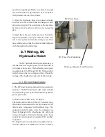
background image

35

2.11 Hydraulic 

Maintenance

Monthly checks:

1. Oil Reservoir - Fluid level should be at the 

venting plug with the hoist in the up position. 

Oil, Chevron automatic transmission fluid, 

“Dexron II” or equivalent.

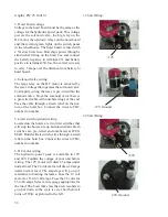
2. Packing gland - Little water should weep 

from the packing.  It should not drip.  If there is 

too much water coming from the packing gland 

tighten each of the cap bolts one full turn.  Run 

the hoist up and down and check for water.  If 

the packing gland cap has bottomed out, add one 

new layer of packing, Wesmar part #09.00749.0

3. Check all wiring and hydraulic lines that may 

catch or snag when the hoist is moving

Summary of Contents for SS395

Page 1: ...STALLATION OPERATION MANUAL WESTERN MARINE ELECTRONICS 14120 NE 200th Street PO Box 7201 Woodinville WA 98072 4001 USA Telephone 425 481 2296 Fax 425 486 0909 Email dsoderberg wesmar com www wesmar co...

Page 2: ...ur way control switch will move the cursor up down left right on the sonar screen By placing the cursor on a target both horizontal and vertical measurements are logged in the space noted by the arrow...

Page 3: ...lection Screens There are four selection screens where adjustments are made Each adjustment can be viewed as the sonar runs to maximize target detection The four selection screens are titled as Wesmar...

Page 4: ...verse 2 Highlight reverse pull the trigger to reverse scan Pull the trigger again to highlight reverse then pull the trigger to reverse As fast as one can pull the trigger two times the scan will reve...

Page 5: ...he scanning speed of the sound beam Speed 1 is for fine resolution Speed 4 is for fast up date Faster speeds may lose single fish targets ZOOM In Screens 1 2 and 3 the cursor can be used as a magnifie...

Page 6: ...ant to go to Trigger the hand controller for the second time to view the screen By triggering the hand controller the third time will place the cursor back into the sonar display COLOR BARS There are...

Page 7: ...he vessel In order for this target to mark the same color at different ranges the receive gain must increase proportionally with range Propagation losses of sound energy will change with frequency sal...

Page 8: ...ping LIMITER The third of the three filters The limiter can be ON or OFF When ON interference from any other sonar sounder equipment on board will not mark on the screen This is accomplished by elimin...

Page 9: ...the white back ground and select 4 to 6 on PALETTE PALETTE Palette deals with target color brightness from blue to red When using a low threshold the screen may by full of blue and green targets Too m...

Page 10: ...eed to be increased SECTOR Profile has its own sector sizes with the center mark straight down TVG Time Variable Gain offsets propagation losses as sound energy moves through the water These losses ar...

Page 11: ...ttom typing make the following settings Select the clip color Lower the threshold to 1 Turn ENHANCE to OFF Turn FILTER to 5 When over hard bottom adjust the near and far gains so the bottom just marks...

Page 12: ...1 6 for more information Audio is only activated after the first range ring This will reduce any audio from noise that is around the boat Audio is extended to the corner of the screen Two types of aud...

Page 13: ...n run with the soundome in the up position Screen 4 Full screen down sounder Note Sounder controls Down Sounder settings BRIGHT Brightness will control the overall intensity of the display TUNING Adju...

Page 14: ...3 0 meter cord with a connector at the end that mates to the bulkhead connect Would you like to have more than one hand con troller Three good locations would be the wheel house flying bridge and or t...

Page 15: ...itors is normally short Use an extension VGA cable to reach the computer control unit if needed Exten sion cable not supplied Fasten the computer control unit in place using the holes in the mounting...

Page 16: ...bles The video cable is typically 5 ft 1 5 meters long The video cable connects to the computer control unit If the video cable is not long enough use a standard VGA extension cable 2 1 6 Audio Line O...

Page 17: ...in use This becomes the minimum length the minimum length is different for the following models Model Minimum Length SS395 E 160 21 in 53 3 cm SS395 H 160 24 in 61 cm SS395 E 110 22 5 in 57 2 cm SS39...

Page 18: ...n 1 meter from the keel The bottom of the seachest must extend down to 1 2 in 33mm up from the keel Fair the seachest for and aft but not to the hull If faired to the hull bubbles will travel down the...

Page 19: ...e inside seachest Fasten the soundome to the soundome tube Assemble hoist Attach hoist to seachest 2 3 1 Calculate Lenth Of Soundome Tube There are two electrical hoist systems One for the 6 in soundo...

Page 20: ...nto the soundome 2 Wrap teflon tape around the threads of the soun dome tube WARNING only use Teflon tape on the threads of the soundome tube Chemical thread sealant will damage the ABS threads of the...

Page 21: ...n 51 mm remain on the other side Tighten the top hoist clamp 3 8 in nuts so the soundome tube is locked in place 5 Place safety clamp directly below the top hoist clamp and tighten bolts 2 3 5 Attach...

Page 22: ...sen the top hoist clamp and push up or down on the soundome tube for the correct measurement Retighten the hoist clamp 6 Slide the safety clamp up to the top hoist clamp Apply ANTI SEIZE to the bolts...

Page 23: ...ther end of the three pin connector to the three pin connector on the switch panel 5 Hoist Control Cable 78 03900 0 The hoist cable is 25 ft 7 6 m long The cable connects the switch panel to the hoist...

Page 24: ...r as it travels down It should stop before the safety clamp comes in contact with the packing gland If it looks like the safety clamp will hit the packing gland unplug the hoist motor Rotate the lead...

Page 25: ...ght packing gland will hold the soundome tube from moving either the fuse will blow or the bronze shear pin will break 2 6 Hydraulic Hoist Installation The hydraulic hoist will require some assembly T...

Page 26: ...4 Slide the tube safety clamp over the soundome tube 5 Slide the tube guide clamp over the soundome tube 2 6 2 Install the soundome 1 Clean the matting surfaces of the soundome and soundome tube flang...

Page 27: ...e strain relief grommet around the sound ome cable Slide the grommet down the cable until it fits snuggly into the top of the hydraulic end cap Bolt the strain relief plate over the grommet 5 Push the...

Page 28: ...urns NOTE When the vessel is back in the water cycle the hoist up and down four times Check the pack ing gland for water It is normal for the packing gland to weep but not drip Tighten if necessary 2...

Page 29: ...hydraulic power pack is avialable in 12V DC and 24V DC Wiring is dif ferent between the two voltage systems Check the voltage of the hydraulic pack unit before wiring 2 7 1 DC hoist board wiring 1 Th...

Page 30: ...ble with numbered lugs at the end Pass the cable through a strain relief on the bot tom of the hoist box Connect the wires to TB2 number to number 5 Limit switch up down wiring Located on the hoists a...

Page 31: ...voltage Voltage to the hoist board is the same voltage that will power the motor and the solenoid valve on the hydraulic power pack Run ships AC power through one of the strain relief fittings on the...

Page 32: ...l is 18 inches 45 5cm Outside the seachest 16 5 inches 42cm 2 Make sure the hoist switch is in the up posi tion 3 Disconnect the upper hoist limit switch wire labeled 27 located on TB2 for DC motors o...

Page 33: ...1 2 9 2 Check hoist soundome travel 1 Lower the soundome push the hoist switch down in the wheelhouse 2 Measure the distance from the bottom of the seachest to the bottom of the soundome under the bo...

Page 34: ...wer a Solenoid valve stuck b Check solenoid wiring c Fluid level in reservoir is too low d Packing gland cap is too tight e Hoist rack is bent f Obstruction in seachest g Reservoir is not vented 3 Hoi...

Page 35: ...Packing gland Little water should weep from the packing It should not drip If there is too much water coming from the packing gland tighten each of the cap bolts one full turn Run the hoist up and do...

Page 36: ...36...

Page 37: ...14120 NE 200th Street Box 7201 Woodinville WA 98072 4001 USA T 425 481 2296 F 425 486 0909 Email sonar wesmar com Web www wesmar com...

Reviews: