background image

Westherm

Propeller Fan Unit Heaters

Models 35 to 110

R

IMW 300.0M/03.02

Supersedes : None
Part number : Q3NSTE830

Installation and Maintenance Manual

GB

F

Summary of Contents for Westherm 110

Page 1: ...Westherm Propeller Fan Unit Heaters Models 35 to 110 R IMW 300 0M 03 02 Supersedes None Part number Q3NSTE830 Installation and Maintenance Manual GB F...

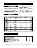
Page 2: ...Dimensional Data and Weight of Options p 7 Installation p 9 Unit Handling p 9 Installation location p 9 Installation instructions p 10 Supply air throw p 11 Water Connections p 12 Water coil connectio...

Page 3: ...ons and experienced with this type of equipment All field wiring must be installed in accordance with the national wiring regulations Ensure the rated voltage of the unit corresponds to the name plate...

Page 4: ...tered letter to the forwarder mentioning clearly the occured damages and a copy of the letter to the manufacturer or its representative Do not stand or transport the unit on its end Temporary storage...

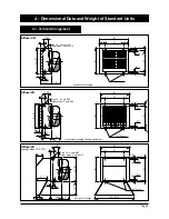
Page 5: ...B H M12 nuts G L L J 170 A x B 70 S C D Size 70 4 nuts M12 Other sizes 2 nuts M12 A B H M12 nuts G L L 64 J A1 C1 170 A x B S C D Size 70 4 nuts M12 Other sizes 2 nuts M12 A B H M12 nuts G L L 64 E B...

Page 6: ...ection Vertical discharge Horizontal discharge Diffuser HP except sizes 70 110 Diffuser HO except sizes 35 70 110 Diffuser HN 4 Dimensional Data and Weight of Standard Units cont d 4 2 Horizontal Arra...

Page 7: ...th bird guard and seal ring to be mounted by others 66 Y Y6 6 Dimensions mm Note The size 110 is equipped with 2 accessory sets of the size 55 1080 x 1870 y ya 500 e x e a x a y y y y y a E a x a 120...

Page 8: ...supplied Weight kg a x a Y a x a Y a 12 50 Position of damper control shaft h x h h 50 2 502 1440 or 940 h4 a 60 a x a 120 a E CJ Arrangement 7 VAGZ h x h h 50 2 502 1440 or 940 h4 a 60 a x a 120 a 1...

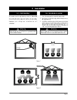
Page 9: ...where vapour from oil or its mist flows into the unit 1 The units are designed to be installed at high position 2 Install the unit in a position having sufficient strength to carry the weight of the...

Page 10: ...aded rods or strengthened screws supplied by the installer see drawings A B 4 The ceiling units with down flow air discharge must be suspended via 4 hangers fixed onto fixing brackets located on the s...

Page 11: ...S L G D The air throw of a propeller fan unit heater is the distance between the unit and the points where the air velocity is no longer felt by the human body approx 0 2 m sec The air throw allows th...

Page 12: ...n between air and water is obtained Flexible hoses are recommended for coil connections in order to ensure a free volume expansion of water pipings To avoid any damage on coil use two spanners to tigh...

Page 13: ...Page 13 7 Water Connections cont d 7 3 Water Pressure Drop...

Page 14: ...Concerning the unit mounted in horizontal arrangement vertical discharge the maximum allowable temperature on the motor is 40 C If the fan is switched off it is important to check that hot water will...

Page 15: ...f1 VAL arrangement Filter removal VAF arrangement The filter box E allows filter removal from one of the four sides 9 Preliminary Checks Before Start up 1 Make sure that system piping has been cleane...

Page 16: ...ours Jean Jaur s 17800 Pons France Tel 33 5 46 92 33 33 Fax 33 5 46 91 26 44 www wesper com With a concern for a constant improvement our products can be modified without notice Photos non contractual...

Reviews: