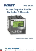
Pro-EC44 2-Loop Graphical Profile Controller & Recorder
Pro-EC44 Product Manual - 59540-2 September 2014
Page 5
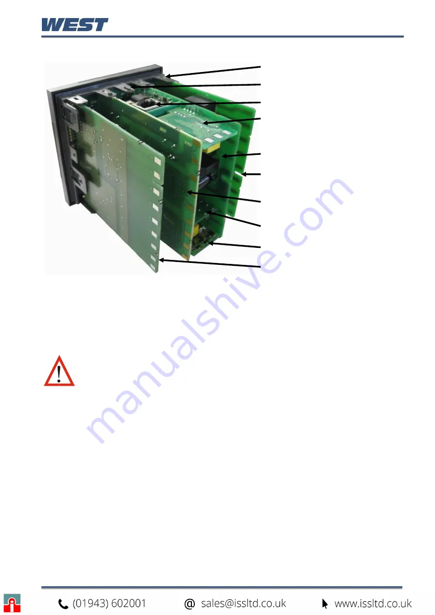
Board Mounting Struts (x4)
Front Panel Removal Latch (x1)
Plug-in Module A
Plug-in Module 3
Power Supply Board
2nd Universal Input & Base
Option 2 Board
1st Universal Input & Base
Option 1 Board
Plug-in Module 1
Plug-in Module 2
USB/Digital Input C Option
Board
Figure 3. Rear view (uncased) & board positions
Preparing to Install or Remove Plug-in Modules
CAUTION:
Before removing the instrument from its housing, ensure that all
power has been removed from the rear terminals. Modules / boards should
be replaced by a technically competent technician.
1. Grip the edges of the front panel (there is a finger grip on each edge) and pull it forwards
approximately 10mm, until the Front Panel Removal Latch prevents further movement.
The purpose of the latch is to prevent removal of the instrument without the use of a tool.
2. The Front Panel Removal Latch must be pushed down to allow removal of the instrument.
Using a tool (e.g. screwdriver or pen tip), press down it down through the front central
ventilation hole. This will release the instrument from the case.
3. The internal boards can now be accessed. Take note of the orientation of the instrument
and boards for subsequent replacement into the housing. The positions of the boards,
their mountings and the Front Panel Removal Latch are shown above.
Summary of Contents for Pro-EC44
Page 1: ...Pro EC44 2 Loop Graphical Profile Controller Recorder Pro EC44 User Guide 59540 2 ...
Page 2: ......
Page 6: ......

