Pro-EC44 2-Loop Graphical Profile Controller & Recorder
Pro-EC44 Product Manual - 59540-2 September 2014
Page 163
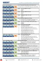
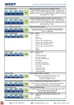
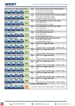
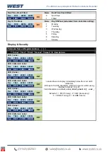
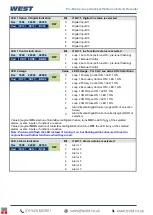
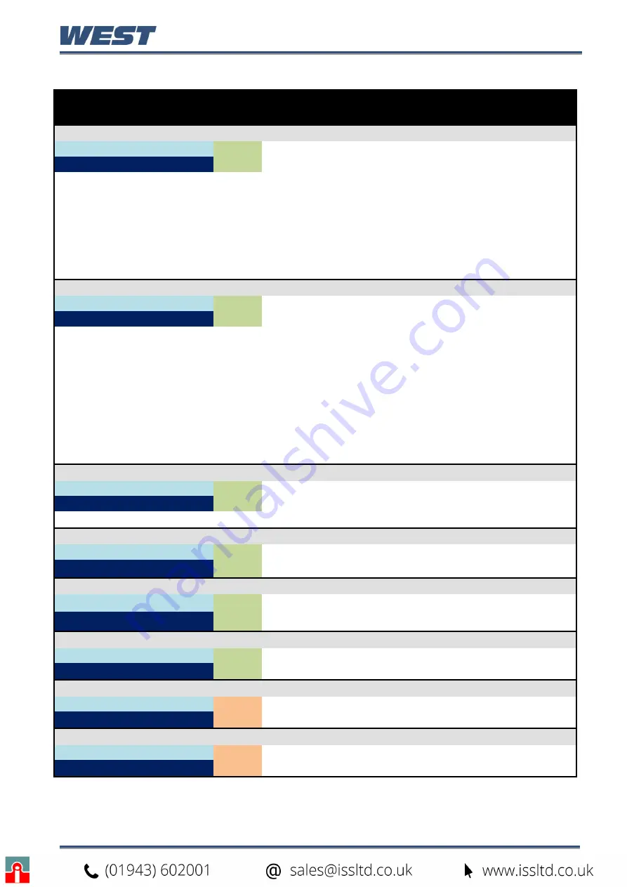
Alarm Parameters
Parameter Name & Register Address
Integer Int +1
Float
Access
Values
& Descriptions
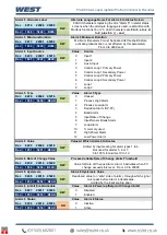
Alarm 1 Input Source
Value
Alarm 1 Source
Dec
6143
22527 45054
RW
0
Input 1
Hex
17FF
57FF
AFFE
1
Input 2
2
Aux A Input
3
Control Loop 1 Primary Power
4
Control Loop 1 Secondary Power
5
Control Loop 2 Primary Power
6
Control Loop 2 Secondary Power
7
Loop 1
8
Loop 2
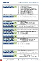
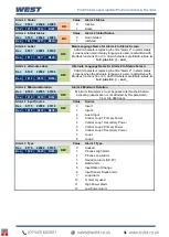
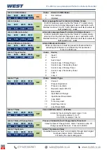
Alarm 1 Type
Value
Alarm 1 Type
Dec
6144
22528 45056
RW
0
Unused
Hex
1800
5800
B000
1
Process High Alarm
2
Process Low Alarm
3
Deviation Alarm (SP-PV)
4
Band Alarm
5
Input Rate of Change
6
Input/Sensor Break Alarm
7
Loop Alarm
10
% memory used
11
High Power Alarm
12
Low Power Alarm
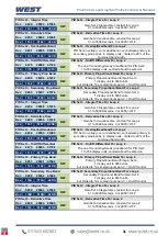
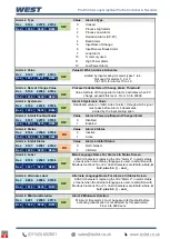
Alarm 1 Value
Value At Which Alarm 1 Activates
Dec
6145
22529 45058
RW
Limited by input scaling for alarm types 1 to 4.
Not used for alarms 5, 6 or 7.
0 to 100% for alarms 10 to 12.
Hex
1801
5801
B002
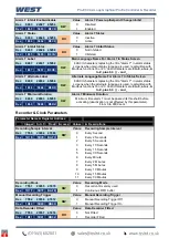
Alarm 1 Rate of Change Value
Process Variable Rate of Change Alarm Threshold
Dec
6150
22534 45068
RW
Value for Rate of Change Alarm. Alarm 1 activates when PV
change exceeds this level. From 0.0 to 99999
Hex
1806
5806
B00C
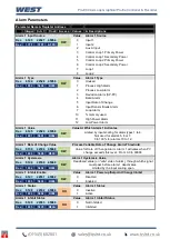
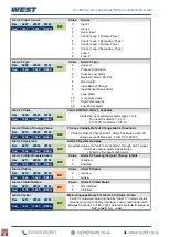
Alarm 1 Hysteresis
Alarm 1 Hysteresis Value
Dec
6146
22530 45060
RW
Deadband value (
on “safe” side of alarm
), through which signal
must pass before alarm 1 deactivates.
Limited by the input scaling span
Hex
1802
5802
B004
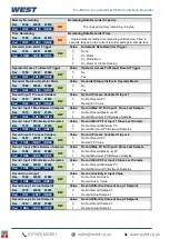
Alarm 1 Inhibit Enable
Value
Alarm 1 Power-up/Setpoint Change Inhibit
Dec
6147
22531 45062
RW
0
Disabled
Hex
1803
5803
B006
1
Enabled
Alarm 1 Status
Value
Alarm 1 Status
Dec
6148
22532 45064
RO
0
Inactive
Hex
1804
5804
B008
1
Active
Alarm 1 Inhibit Status
Value
Alarm 1 Inhibit Status
Dec
6149
22533 45066
RO
0
Not Inhibited
Hex
1805
5805
B00A
1
Inhibited
Summary of Contents for Pro-EC44
Page 1: ...Pro EC44 2 Loop Graphical Profile Controller Recorder Pro EC44 User Guide 59540 2 ...
Page 2: ......
Page 6: ......

