Pro-EC44 2-Loop Graphical Profile Controller & Recorder
Pro-EC44 Product Manual - 59540-2 September 2014
Page 13
Connections and Wiring
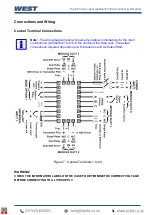
Central Terminal Connections
Note:
The wiring diagram below shows all possible combinations to the main
connections (numbered 1 to 24) in the centre of the case rear. The actual
connections required depends upon the features and modules fitted.
.
Figure 7. Central Terminals 1 to 24
WARNING:
CHECK THE INFORMATION LABEL ON THE CASE TO DETERMINE THE CORRECT VOLTAGE
BEFORE CONNECTING TO A LIVE SUPPLY.
Summary of Contents for Pro-EC44
Page 1: ...Pro EC44 2 Loop Graphical Profile Controller Recorder Pro EC44 User Guide 59540 2 ...
Page 2: ......
Page 6: ......


